Description of the design of the A15SMS and F16D3 DAEWOO NEXIA N150 engines. Some features of Daewoo Nexia Engines Daewoo Nexia A15SMS
Sedan Deously Nexia is very popular in our country, as it combines high level reliability, safety and acceptable cost. This car is perfectly sold even in the factory configuration, but many car owners perform tuning, allowing you to make cars unique and more expressive.
Tuning Deo Nexia allows you to change the machine to be unrecognizable by installing elements such as:
- new thresholds;
- alloy wheels;
- spoiler;
- original bumper and much more.
In the cabin you can also change a lot:
- station seats replace to products with support model;
- change the color of the backlight of the dashboard;
- add extra backlight to the salon;
- drag plastic, etc.
Engine tuning is a topic for a separate conversation. For example, you can replace the camshaft and firmware to deo, significantly increasing the car dynamics.
Daewoo. Nexia.
The difficulties of tuning the power unit of this car are associated with the complexity of buying high-quality spare parts for obsolete and weak Engine. Some are at all consider tuning of a 1,5-liter motor with a capacity of 75 hp A completely meaningless check. They explain this as the maximum possible increase in capacity in 30 hp. and a significant reduction in the motor test. Not all owners Daewoo Nexia. Agree from this point of view.
You can purchase a unique tuning kit to replace the piston group and the GRM of German production, but such details are very rare and is unreasonably expensive. It is much more profitable to buy, configure and install new engine Increased power.

Professional auto mechanics note that when tuning the engine deo Nexia can be installed a compressor that will begged the fuel and air mixture into the motor. It is important to competently set the pressure issued by this device in order not to fail the power unit.
As practice shows, not even the most expensive, but very reliable domestic compressors can be supplied to the engine cylinders, the working mixture under pressure is much higher than atmospheric. For regular non-zone engines, excessive increase can be fatal. Overgrowing with an increase horse power, Local overheating will arise, which may not withstand shafts, connecting rods and pistons.
If you plan to make a tuning of Motor deo Nexia by mounting a mechanical supercharger, do not tune it to a pressure of more than 0.5 atm.
As for deeper technical tuning Nexia power unit, it is rarely performed. In this case, such actions can be performed:

Tuning Motor Deo Nexia requires the installation of the following spare parts:
- forged pistons;
- rods of reinforced design;
- light flywheel;
- lightweight and reinforced timing.
It is impossible to do without enhanced clutch and brake shoes Increased wear resistance.
Serious tuning of 1.5-liter non-dissimi motor engines are mainly strengths, and simple motorists can be limited to chip tuning, which we will describe below.
Appearance
Many motorists start tuning Deously Nexia not with improved technical characteristics, and with the transformation of the exterior, which involves the installation of bodyworks, spoilers, tinting and other parts. Installation of all this completely transforms the vehicle and slightly improves the dynamics (by increasing the aerodynamic parameters).

All work on tuning the appearance of the car can be held in the garage, without giving money to masters in service centers. You only need to buy new bumpers, spoiler and thresholds, and install them instead of regular body parts using a set of conventional keys and screwdrivers.
Tuning Far
The tuning headlights of Deo Nexia enjoys popularity. For example, instead you can install bosenon blocks, and parking lights Transfer into turn signals. In this bumper, you can additionally hind the washers. By the same principle tuning the rear lights. You can also use another tuning method, which suggests the toning of the rear lights with a special film or varnish.
Installation of deflectors

Deflectors on the hood and side windows give the engine of originality and make it more elegant. In addition, these accessories add practicality, since after they are installed on the side windows you will be able to fit the glass in the rain and snow, airing the interior and preventing fogging.
As for the so-called mufflee (deflector on the hood), they do not affect the dynamics, but do appearance Deously Nexia is more aggressive. In addition, thus, you protect the hood from small chips and other damage from stones and flying out of the wheels in front of ride cars.
Tuning Salon Daewoo. Nexia.
Salon of the car deo Nexia is made not the best way, so everyone without exception, the owner dreams of modernizing it. In this case, everything rests on your capabilities and fantasy. If you have money, you can replace almost everything:
- seats;
- upholstery;
- backlight and much more.

Drag into the skin or any other material can do the door cards, the seats themselves and even dashboard. It is all silent, but the result usually exceeds all expectations. The new salon Deo Nexia will become unrecognizable and unique.
Dashboard
Give an originality salon allows a new dashboard with a liquid crystal display. As a rule, brightness adjustment is usually provided that allows you to adjust the panel to itself. You can additionally install the rain sensor that will automatically turn on the wipers at the right moment, and you do not have to be distracted from the road. If you have a little money, you can disassemble the dashboard and replace the backlight in it on any color you like. There is nothing difficult in this if you have free time and some skills in the disassembly of automotive salons.
Seat replacement
Chairs in Daewoo Nexia are far from the most comfortable, so if possible, they are better lured. Instead of standard products, you can install new ones from recaro or other firm equipped with side support. Sitting in such chairs is much more convenient.

You can tuning the car with your own hands as you like, because there is no limit fantasy - everything rests on money. You can see in this article or on the Internet photos of tunned nexies and choose the option that suits you to taste.
You can install this practical element in your deo Nexia yourself in garage conditions. Just buy an armrest at the car market or in a specialized store, and make it installation according to the applied instructions. If it does not turn out, find other car owners on the Internet, as other car owners are coping with this task. As a rule, in 5-10 minutes you can install the armrest, which will add to you comfort.

Chip Tuning Deo Nexia do it yourself
Chip-tuning engine deo Nexia is a simple task. In most cases, the KDAC_ZXJN brand control units are installed on these machines. Before starting tuning, make sure vehicleso as not to aggravate breakdowns.
What will required?
For chip tuning you will need the next set of things:

- Willem programmer (he is not cheap, so just ask him for a while).
- Transition fee from the chip on the ECU connector.
- WinBond 27C512 chip for recording new firmware.
- Firmware.
You can buy everything you need and find on specialized forums on deo Nexia.
How to conduct chip tuning?
Connect the programmer to the computer, acting according to the instructions, and download the firmware on the microcircuit. Next, you need to remove the terminals from the battery under the hood of Deo Nexia and find the control unit located at the right front door behind the trim.
Remove the block (you can not disconnect), unscrew the pair of bolts from above, disconnect the chip of the blue color and insert a new chip with an earlier firmware. To do without soldering, use the adapter fee.

Set the block cover and insert it back. Install the terminals and turn the key in the ignition, but do not start the car. You must hear the work of the benzonasos (this is a sign of the correctness of the actions performed). If everything is so, start the engine and check its work for the absence of detonations and uneven work. If something is wrong, try to pour another firmware to the chip, and if none is suitable, return a regular chip in place.
Chevrolet Engine Lanos 1.5 A liter with a capacity of 86 horsepower is essentially developing Opel engineers. This is a gasoline atmospheric from the A15SMS series, which can be found in Deu Nexia. Simple and reliable 8-valve motor has a number constructive featureswe will talk about more about. 
Chevrolet Engine Device Lanos 1.5
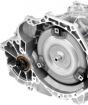
LANOS 1.5 engine gasoline, four-stroke, four-cylinder, row, eight-block, with upper arrangement distribution Vala.. Location B. motor compartment transverse. Cylinder Operation: 1-3-4-2, countdown - from pulley auxiliary aggregates. The power system is a phased distributed fuel injection (Euro-3 toxicity standards). Motor has a cast iron block of cylinders.
Engine with gearbox and clutch form force aggregate - Single block, fixed in the engine compartment on three elastic rubber-metal supports. The right support is attached to the bracket located on the front wall of the cylinder block, and the left and rear - to the gearbox.
Chevrolet Engine Cylinder Block Head 1.5

Chevrolet Lanos 8 valves casting cylinder head from aluminum alloy, total for all four cylinders. The head is centered on the block with two sleeves and is attached to ten bolts. Sealing gasket is installed between the block and head of the cylinder block.
On the opposite sides of the cylinder head, the windows of intake and outlet channels are located. The saddles and guide sleeves of the valves are pressed into the cylinder head. The valve closes under the action of one spring. It rests on the lower end to the washer, and the top is on the plate held by two crumbs. Collapshedral creaks have a shape of a truncated cone, and on their inner surface, puzzles are made in the valve rods. Prolve valves in motion camshaft. Camshaft - The cast iron, rotates on five supports (bearings) in the aluminum housing of bearings, which is attached to the top of the cylinder head.
Driver GRM Engine Chevrolet Lanos 1.5

The lanos 8-valve camshaft camshaft drive is carried out by a gear strap from crankshaft. The valves are powered by camshafts through the pressure levers, which are led by one shoulder on the gap hydrocomators, and the other shoulders through the guide washers are on the valve rods.
The engine has hydrocompensatorswhich are self-regulating piping leverage supports. Under the action of oil filling the inner cavity of the compensator, the compensator plunger selects the gap in the valve drive. The use of hydrocomathers in the valve drive reduces the noise of the gas distribution mechanism, and also excludes its maintenance.
In the event of a cliff of the valve belt, the oppression is definitely! In addition to other features, it can be noted that the timing belt rotates the pump (water pump). Replacing the belt is carried out every 60,000 kilometers, the pump must be changed once every 120 thousand mileage kilometers.
Engine specifications Lanos 1.5 8 valves
- Working volume - 1498 cm3
- Number of cylinders - 4
- Number of valves - 8
- Cylinder diameter - 76,5 mm
- Piston stroke - 81.5 mm
- Timber drive - belt
- Power hp - 86 at 5800 vol. in min.
- Torque - 130 nm at 3400 vol. in min.
- Maximum speed - 172 km / h
- Acceleration until the first hundred - 12.5 seconds
- Fuel type - gasoline AI-92
- Fuel consumption in the city - 10.4 liters
- Fuel consumption in a mixed cycle - 6.7 liters
- Fuel consumption on the highway - 5.2 liters
Chevrolet Lanos, he was done by Daewoo Lanos in huge quantities in Korea, China, India, Poland, Ukraine ... Often, the model could have different names but constructively this is the same budget car.
Chevrolet 1.5 A15SMS engine is designed for Chevrolet Lanos cars (Daewoo Lanos).
Features. The A15SMS engine is the further developed engine of the G15MF, which was installed on Daewoo Nexia until restyling. The engine acquired some improvements, such as: valve cover made of special plastic, appeared additional sensors The engine control system, the inlet receiver of a different form, appeared an electronic ignition module. The engine was installed with two catalytic exhaust gases and two oxygen concentration sensors. This made it possible to make compliance with the ecological standards of Euro 3. Also additionally on the power unit installed a camshaft position sensor and a detonation sensor.
The engine engine is similar to engines used for installation on KADETT E and ASCONA C, so it is difficult to wait for the outstanding characteristics from this motor. Therefore, the engine does not boast of low fuel consumption.
GRM - belt drive. When cutting the belt valves. In the head of the establishment of hydrocomathers, the adjustment of the gaps is not needed.
It is worth noting that this engine It has a fairly good resource. Motor resource 1.5 A15SMS about 200-250 thousand km. There are no separations of more than 300 thousand km without overhaul.
Chevrolet 1.5 A15SMS Engine Characteristics Lanos
| Parameter | Value |
|---|---|
| Configuration | L. |
| Number of cylinders | 4 |
| Volume, L. | 1,498 |
| Cylinder diameter, mm | 76,5 |
| Piston stroke, mm | 81,5 |
| Compression ratio | 9,5 |
| Number of valves on the cylinder | 2 (1-inlet; 1-release) |
| Gas distribution mechanism | Sohc. |
| The order of the cylinders | 1-3-4-2 |
| Rated motor power / at a crankshaft rotation frequency | 63 kW - (86 hp) / 5800 rpm |
| Maximum torque / at the rotational speed of the crankshaft | 130 N M / 3400 rpm |
| Supply system | Distributed injection with electronic control |
| Recommended minimum octane gasoline number | 92 |
| Environmental norms | Euro 3. |
| Weight, kg | - |
Design
Four-stroke four-cylinder petrol with an electronic fuel injection and ignition control system, with inline cylinders and pistons rotating one common crankshaft, with the upper arrangement of one camshaft. Engine has liquid system Cooling a closed type with forced circulation. Lubrication system - combined.
The cylinder block is made of cast iron, the cylinders are boring directly in the body body. Crankshaft cast iron with eight counterweights. Steel rods, forged. Aluminum pistons with shifted 0.7mm holes under the piston finger along the axis of symmetry towards the rear wall of the cylinder block. GBC aluminum, eight-glovenaya. Valves are equipped with one spring and are powered through push levers.
Service
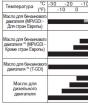
Replacing the oil in the engine A15SMS 1.5. Oil replacement B. Chevrolet Lanos. The 1.5 liter A15SMS engine produces every 10 thousand km (some car owners produce oil replacement every 7-8 thousand km). Oil volume in engine 3.75 liters. When the oil is replaced together with the filter, there are 3.3-3.5 liters of oil, if not changing the filter, then it is slightly less. Oil suitable by SAE - 5W30 and 5W40.
Replacing the timing belt. By regulations maintenanceThe verification of the status of the timing belt should be carried out in 50 thousand km. The belt is subject to a replacement after 60 thousand km of mileage. With the replacement of the timing belt, it is necessary to replace the tensioning roller.
Daewoo Nexia 2008. There are couples from under the lid of the expansion tank (white smoke)
Breakdown gBC pads
The most frequent answer to such a problem, it is exhausting gasket cylinder (cylinder head), if you are not difficult to disassemble the engine probably the first idea will change this gasket. But imagine that there are two more reasons that antifreeze squeezes out of the system.
1- This is a height plug in the system of the coolant, because of it, not only the stove in the cabin may not work, and this is already a sign of the plug in the coolant, provided that the fluid level is normal, but also not the correct operation of the thermostat is possible. What can lead to an increase in pressure in the cooling system. Well, the extrusion of antifreeze.
2 is a problem associated with the expansion barrel, well, and the smart lid of this tank.
To improve the circulation of coolant over the engine, when the motor starts, a small pump pressure is created, which increases the efficiency of the cooling system. If there is no sufficient pressure in the coolant system, the engine will quickly heat up. What can lead to boiling or decomposition of antifreeze. When the decomposition of antifreeze pairs are looking for weak spots. Such as wooden rubber sealing rings of the cooling system, bad nozzles, not tightly tightly lid expansion tank or radiator.
GBC is of course also not a minor problem, but it is also quite possible to diagnose and as it turned out very simple.
We start the engine, open the lid of the expansion tank, if on idling You can see bubbles that go from the main hose, this one of the two or is broken by an air traffic jam, or a problem with the gasket of the CHC.
If this is a air traffic jam, then rejoicing and waiting for some time from it can be delivered, the most effective procedure is very complex in the description as it is necessary to conduct a number of consecutive actions and better to show them to the chamber.
If there are no traffic jams and the problem with the GBC, then you will have a constant or weak drilling in the expansion barrel or the level of antifreeze will gradually leave.
If you have a coolant somewhere and there are no traces on the engine, then there may be a coolant to be either in the cylinder, or in the silencer, which also often happens. This speaks about the problem with the GBC.
Faults of the expansion tank
First, it is necessary to look at the leaks of antifreeze on the barrel, there are three problems with it:
1- The lid of the expansion tank (covered the cover of the cover) passes the air, the deformation of the lid of the Republic of Belarus - the expansion tank is only a replacement for the original.
2- Torn thread of the lid of the expansion tank, in this case, the new cover will not help for a long time!
The 3- expansion barrels has a flow or burst on a seam, which from an increase in pressure in the engine system system manifests itself, there are such cases that as cooling in DVS The gap is joined and the coolant stops squeezing.
4- air drows (happens, but rarely)
The most important thing is the visual inspection on the subject and places of leaks, and checks on damage to hoses.
Pay attention to the thread on which the tank cover was twisted.
It happens that if you tighten the lid, it rises crooked and the liquid easily leaves the tank. If you look at the tank thread, then it is not clear the whole or not, but if it turned out to be high on one side, it is all the ripple.
Other reasons
1. White emulsion (foam) on the probe check of the oil level or on the lid of the oil-tank neck speaks of the coolant hit to the lubrication system, most likely through the hole in the cylinder head laying. Sometimes, however, rarely the gasket is whole and unharmed, and the leakage is due to cracks in the block itself. But in any case, in the presence of a white emulsion in the lubrication system, it is necessary to beat the alarm, and even better to take a tool into the hands and eliminate the malfunction.
2. White smoke from exhaust pipe When the engine is running, indicates the penetration of the coolant into the cylinder (cylinders) of the engine. At the same time, its level decreases, as it partially "flies into the pipe". The exhaust of the car can be white when driving the engine, a large number of condensate and large air humidity is not a malfunction, but if the "smoke" is always a lot - it is worth thinking.
3. Oil spots on the surface of the coolant in the expansion tank or in the radiator speak of the penetration of oil to where it is not supposed.
The reason is likely to malfunction of the head of the cylinder head. At least check it stands.
4. Bubbles overlooking expansion tank Or the radiator indicate penetration into the coolant exhaust gases. Somewhere holes, and most likely it is in the block laying the block. A certain amount of bubbles can appear when replacing the coolant - this is normal, but if the toosol is constantly "bubble" - it means something is impudent.
five . The oil-wave neck closed
6. Tosol leaves from under the studs of fastening the exhaust manifold
8. Water from the radiator falls into the cylinder block - it is necessary to replace the radiator
Complexity
Without toolsNot indicated
The engine control system consists of an electronic control unit (ECU), the sensors of the operation of the engine and the car, as well as executive devices.
Elements electronic system Engine control F16D3:
1* - phase sensor;
2
3*
4* - diagnostic shoe;
5*
6* - knock sensor;
7
8* - speed sensor;
9*
10*
11 - accumulator battery;
12
13*
14 - ignition coils;
15*
16*
17* - spark plug;
18* - Diagnostic oxygen concentration sensor.
Note:
*

Scheme of electronic engine control system F16D3:
1 - accumulator battery;
2 - ignition switch;
3 - ignition relay;
4 - ECU;
5 - diagnostic shoe;
6 - a combination of instruments;
7 - air conditioner switch;
8
9 - air conditioning compressor;
10 - wheel rotation speed sensor;
11
12 - air conditioner refrigerant pressure sensor;
13
14 - control sensor concentration of oxygen;
15 - crankshaft position sensor;
16 - ignition coils;
17
18 - nozzle;
19 - phase sensor;
20 - absolute air pressure sensor on the inlet;
21
22 - knock sensor;
23 - valve of the system of changes in the length of the intake path;
24 - adsorber blowing valve;
25 - coolant temperature sensor;
26 - throttle position sensor;
27 - Regulator idle move;
28
29
30
31 - fuel pump relay;
32 - The fuel pump node.

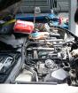
Elements of the electronic engine control system A15SMS:
1* - crankshaft position sensor;
2 - air temperature sensor on the inlet into the engine;
3 - phase sensor;
4* - throttle position sensor;
5* - diagnostic shoe;
6* - electronic control unit;
7 - absolute air pressure sensor on the inlet;
8* - diagnostic oxygen concentration sensor;
9* - knock sensor;
10* - Control lamp of the control system;
11* - mounting block fuses and relays;
12 - Sensor of the uneven road;
13* - speed sensor;
14 - accumulator battery;
15 - ignition coil;
16* - coolant temperature sensor;
17* - control sensor concentration of oxygen;
18* - spark plug.
Note:
* - The element in the photo is not visible.

Scheme of electronic engine control system A15SMS:
1 - accumulator battery;
2 - ignition switch;
3 - ECU;
4 - diagnostic shoe;
5a, 5b.- absolute air pressure sensor on the inlet;
6 - air temperature sensor on the inlet;
7 - coolant temperature sensor;
8 - high speed of the cooling system fan rotation;
9 - relay low speed of the cooling system fan;
10 - cooling system fan;
11 - knock sensor;
12 - car speed sensor;
13 - a combination of instruments;
14 - phase sensor;
15 - managing and diagnostic oxygen concentration sensors;
16 - Sensor of the uneven road;
17 - air conditioner switch;
18 - air conditioner compressor relay;
19 - air conditioning compressor;
20 - fuel pump relay;
21 - the fuel pump node;
22a, 22b - adsorber blowing valve;
23 - ignition coil;
24 - valve recycling of exhaust gases;
25 - idle regulator;
26 - throttle position sensor;
27 - nozzles;
28 - Crankshaft position sensor.
ECU (controller) represents a mini computer special purpose. It includes an operational storage device (RAM) and a programmable constant storage device (PPZ). RAM is used by the microprocessor for temporary storage of current information about the operation of the engine (measured parameters) and calculated data. From RAM, the engine control unit takes the program and source data for processing. In RAM also recorded the codes of faults. This memory is energy-dependent, i.e. When the electrical power stops (disable rechargeable battery Or disconnecting the wiring harness blocks) its contents is erased. PPZA stores the engine control program, which contains a sequence of working commands (algorithms) and calibration data - settings. PPZ is non-volatile, i.e. The contents of the memory does not change when the power is turned off. The computer receives information from the system sensors and controls the actuators, such as the fuel pump and nozzles, the ignition coil, the ignition regulator, the heating element of the oxygen concentration sensor, the adsorber purge valve, the exhaust gas recycling valve, the valve of the inlet path valve (on the F16D3 motor ), air conditioning compressor coupling, cooling system fan.

ECU (controller) engine F16D3

ECU (controller) engine A15SMS
Electronic control unit on the car with the engine F16D3 is located in open space Before the battery, and on the car with the A15SMS engine - in the car's cabin under the instrument panel to the right (under the upholstery of the sidewall).

Placing the ECU (controller) of the engine F16D3

Accommodation ECU (controller) A15SMS engine
In addition to supplying power supply to sensors and control of actuator performing devices, the ECU performs the diagnostic functions of the engine control system (side diagnostic system): Defines the presence of faults of the elements in the system, includes a fault control lamp in the instrument combination and saves fault codes in its memory. When a malfunction is detected, in order to avoid negative consequences (the troughing of the pistons due to detonation, damage to the catalytic neutralizer in the event of skips of ignition of the fuel-air mixture, exceeding the limit values \u200b\u200bfor the toxicity of exhaust gases, etc.), the computer translates the system for emergency modes of operation. Their essence is that when the sensor or its circuit fails, the engine control unit applies the replacement data stored in its memory.
Engine control system malfunction control lamp Located in a combination of instruments.

Placing the control lamp of the engine control system in the instrument combination
If the system is properly, then when the ignition is turned on, the test lamp should turn around. Thus, the computer checks the function of the lamp and the control circuit. After starting the engine, the test lamp should go out if there are no conditions for its inclusion in the memory of the computer. Turning on the lamp when operating the engine informs the driver that the onboard diagnostic system has detected a malfunction, and the further movement of the car occurs in emergency mode. At the same time, some of the engine operation parameters (power, pickup, economy) can worsen, but the movement with such faults is possible, and the car can easily reach a hundred.
If the fault was temporary, the computer turns off the lamp for three trips without faults.
Fault codes (even if the lamp went out) remain in the memory of the unit and can be read using a special diagnostic instrument - the scanner connected to the diagnostic shoe.
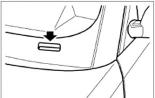
Pad diagnostic (diagnostic connector) Located in the cabin of the car under the instrument panel on the right (under the upholstery of the sidewall).

Placing a diagnostic connector
To access the diagnostic shoe, remove the upholstery upholstery cap.

Access to the diagnostic connector
When deleting fault codes from the electronic unit's memory using a diagnostic device, the fault control lamp in the instrument combinations goes out.
Control system sensors give the computer information about the parameters of the engine and the car, on the basis of which it calculates the moment, duration and order of opening fuel injectors, moment and order of sparking.
Crankshaft position sensor On the engine F16D3 is located on the front wall of the cylinder block under oil filter, and on the A15SMS engine - on the oil pump housing.

Engine crankshaft position sensor F16D3

A15SMS Engine Crankshaft Position Sensor
The sensor displays the control unit information about the speed and angular position of the crankshaft. The sensor is an inductive type, responds to passing near its core of the teeth of the specifying disk attached to the cheek of the crankshaft of the 4th cylinder - on the engine F16D3 or combined with the drive of the auxiliary aggregates - on the A15SMS engine. The teeth are located on the disk with an interval of 6 °. To determine the position of the crankshaft, two teeth out of 60 cut, forming a wide groove. When this groove passes by the sensor, the so-called "reference" synchronization pulse is generated.
The installation gap between the core of the sensor and the peaks of the teeth is approximately 1.3 mm. When the specifying disk is rotated, the magnetic flux in the sensor magnetic core - in its winding, the voltage pulses of the AC voltage are supplied. By the amount and frequency of these pulses, the ECU calculates the phase and the duration of the nozzle control pulses and the ignition coils.

The location of the crankshaft position sensor on the engine F16D3:
1 - Carter pallet;
2 - cylinder block;
3 - sensor socket;
4 - Sensor sensor disk.
Phase sensor (camshaft position) On the engine F16D3 is attached to the right end of the cylinder head next to the pulley of the camshaft of the exhaust valve valves. The phase sensor on the A15SMS engine is fixed on the rear wall of the camshaft bearings chassis next to the camshaft of the camshaft.
The ECU phase sensor signal uses for coordinating fuel injection processes in accordance with the order of the cylinders. The principle of the sensor is based on the Hall effect. To determine the position of the first cylinder piston during the working clock on the engine F16D3, the phase sensor responds to the passage of the protrusion performed on the end of the valve camshaft pulley.

F16D3 motor phases sensor

The mutual position of the phase sensor and the valve valve camshaft pulley on the F16D3 engine (for clarity is shown on dismantled items):
1 - camshaft pulley;
2 - protrusion;
3 - sensor;
4 - Plate for fastening the sensor.
On the A15SMS engine, the sensor responds to the passage of the tide made on the distribution shaft toe.

Engine Sensor A15SMS
Depending on the angular position of the shaft, the sensor displays the rectangular pulses of the voltage on the control unit. of different levels. Based on the output signals of the crankshaft position sensors and distribution shafts, the control unit sets the ignition advance angle and determines the cylinder in which the fuel should be applied. At the failure of the phase sensor, the computer switches to the fuel injection mode.
Cooling fluid temperature sensor On the engine F16D3, screwed into the threaded hole of the rear wall of the cylinder head, between the air supply channels of the 1st and 2nd cylinders. On the A15SMS engine, the sensor is installed in the left end of the cylinder head. The sensor rod is washed by coolant circulating through the cylinder head cooling shirt.

Engine coolant temperature sensor F16D3 and A15SMS
The sensor is a thermistor with a negative temperature coefficient, i.e. Its resistance decreases with increasing temperature. The ECU submits to the sensor through the resistor stabilized voltage +5.0 V and the voltage drop on the sensor calculates the temperature of the coolant, the values \u200b\u200bof which are used to adjust the fuel supply and the ignition advance angle.
Throttle position sensor Mounted on the axis of the throttle and is a potentiometric type resistor.
One end of its resistive element from the computer is supplied to the stabilized voltage +5.0 V, and the other end is connected to the "mass" of the electronic unit. From the third output of the potentiometer (slider), which is connected to the axis of the throttle, the signal is removed for the control unit. Periodically measuring the output voltage of the sensor signal, the ECU determines the current position of the throttle to calculate the ignition advance angle and the duration of the fuel injection pulses, as well as to control the idle regulator.

F16D3 and A15SMS engine throttle position sensor
Absolute Pressure Pressure Sensor (Air Performance)it evaluates changes in air pressure in the inlet pipe receiver, which depend on the load on the engine and the frequency of rotation of its crankshaft, and converts them to the output voltage signals. According to these signals, the ECU defines the amount of air entered the engine and calculates the required amount of fuel. To feed more fuel with a large opening corner of the throttle damper (permission in the intake pipeline insignificant), the ECU increases the operation time of the fuel injectors. With a decrease in the opening angle of the throttle, the vacuum in the inlet pipeline increases both the ECU, processing the signal, reduces the operation time of the nozzles. The absolute air pressure sensor in the inlet pipelines allows the computer to make adjustments to the operation of the engine when the atmospheric pressure changes depending on the height above sea level.
By car with the engine F16D3, the absolute air pressure sensor is attached to the housing of the inlet pipeline and is connected by the tube with its receiver.

The absolute air pressure sensor on the inlet used on the Engines F16D3 and A15SMS
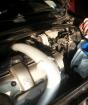
On a car with an A15SMS engine, two versions of the absolute air pressure sensors are used, which are attached to the front panel and are connected to the receiver of the tube inlet pipe. With the first version, the sensor is exactly the same as on the car with the F16D3 engine (see photo above). With the second version, the other sensor.

The absolute air pressure sensor on the inlet used by car with A15SMS engine
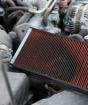
Air temperature sensor on inlet The car with the engine F16D3 is mounted in the corrugated sleeve of air supply to the throttle node. By car with an A15SMS engine, the sensor is mounted in the lid air filter. The sensor is a thermistor (with the same electrical characteristics as a coolant temperature sensor), which changes its resistance depending on the air temperature. ECU via the resistor delivers the stabilized voltage to the sensor +5.0 V and measures the change in the signal level to determine the temperature inlet air. The signal level is high when the air in the pipe is cold, and low when the air is hot. The information obtained from the sensor, the ECU takes into account when calculating the air flow rate for the correction of fuel supply and the ignition advance angle.

Placing the air temperature sensor F16D3

A15SMS engine air temperature sensor
Knock sensor On both engines, fastened on the rear wall of the cylinder block in the zone of the 3rd cylinder.

Engine detonation sensor F16D3 and A15SMS
The piezoceramic sensitive element of the detonation sensor generates an alternating voltage signal, the amplitude and frequency of which correspond to the parameters of the vibration of the engine cylinder block. In the event of detonation, the amplitude of the vibrations of a certain frequency increases. At the same time, the ECU controls the ignition ahead in the direction of the later ignition to suppress the detonation.
In the control system of both engines, two oxygen concentration sensors are used - control and diagnostic.
Oxygen concentration control sensor On both engines installed in the graduate manifold.

F16D3 and A15SMS Oxygen Oxygen Concentration Sensors:
1 - manager;
2 - Diagnostic.
The sensor is a galvanic current source, the output voltage of which depends on the concentration of oxygen in the surrounding sensor medium. According to the signal from the sensor on the presence of oxygen in the exhaust gases, the ECU corrects the fuel supply by nozzles so that the composition of the working mixture is optimal for the efficient operation of the catalytic neutralizer of exhaust gases. Oxygen contained in the exhaust gases after joining chemical reaction The sensor electrodes create the potential difference at the output of the sensor, varying from about 0.1 to 0.9 V.
The low level of the signal corresponds to the poor mixture (the presence of oxygen), and the high level is rich (oxygen is absent). When the sensor is in a cold condition, the sensor output is missing, because Its internal resistance in this state is very high - a few MOM (the engine control system works on the open circuit). For normal operation, the temperature of the oxygen concentration sensor should be no less than 300 ° C. With the aim of quick warm warming Sensor After starting the engine, the heating element is built into the sensor, which controls the computer. As the sensor resistance is heated, the sensor drops and it begins to generate the output signal. Then the ECU begins to take into account the oxygen concentration sensor signal for controlling the fuel supplies in a closed circuit mode.
The oxygen concentration sensor may be "poisoned" as a result of the use of ethyl gasoline or use when assembling the engine of sealants containing in large quantities of silicon (silicon compounds) with high volatility. Silicone evaporation can get through the crankcase ventilation system into the engine combustion chamber. The presence of lead or silicon compounds in the exhaust gases can lead to the output of the sensor. In the event of the failure of the sensor or its circuits, the ECU controls the fuel feed on the open circuit.
Diagnostic oxygen concentration sensor By car with the F16D3 engine installed after a catalytic neutralizer in the intermediate tube of the exhaust gas release system. By car with an A15SMS engine, the sensor is installed in the pipe of an additional silencer after an additional catalytic neutralizer. The main function of the sensor is to assess the efficiency of the catalytic neutralizer of exhaust gases. The signal generated by the sensor indicates the presence of oxygen in the exhaust gases after a catalytic neutralizer. If the catalytic neutralizer works normally, the readings of the diagnostic sensor will differ significantly from the testimony of the control sensor. The principle of operation of the diagnostic sensor is the same as the control sensor of the oxygen concentration sensor.
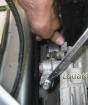
Car speed sensor Installed on the gearbox clutch cartridge, next to the gear shift mechanism.

Car speed sensor
The principle of the speed sensor is based on the Hall effect. The gear of the sensor drive is in engaging with the gear installed on the differential box. The sensor issues rectangular voltage pulses to the ECU with a frequency proportional to the speed of rotation of the drive wheels. The number of sensor pulses is proportional to the path traveled by the car. ECU determines the speed of the car in the frequency of pulses.
In the engine control system F16D3 applies wheel rotation speed sensorwhich issues information electronic block Control.

Wheel rotation speed sensor
The sensor is fixed by swivel fist left front wheel. The sensor is inductive type, reacts to passing near its core of the teeth of the specifying disk, made on the body of the exterior hinge drive of the left wheel.

Wheel rotation speed sensor by car with F16D3 engine
In the A15SMS motor control system applies sensor uneven expensiveMounted in the engine compartment on the left cup of mudguard.

Sensor uneven expensive
The uneven road sensor is designed to measure the amplitude of the oscillations of the body. Variable load on the transmission arising when driving on an uneven road affects angular speed Rotation of the crankshaft engine. At the same time, the oscillations of the rotational speed of the crankshaft are similar to similar oscillations arising from the ignition of ignition of the fuel and air mixture in the engine cylinders. In this case, to prevent false ignition ignition detection in the cylinders of the ECU, turns off this function of the on-board diagnostic system when the sensor signal is exceeded by a certain threshold.
Ignition system Included in the engine control system and consists of a ignition coil (on the engine F16D3 - 2 pcs.), high voltage wires and ignition candles. In operation, the system does not require maintenance and regulation, with the exception of replacing candles. The current control in the primary windings of the coils performs the ECU depending on the engine operation mode. To the conclusions of secondary (high-voltage) windings of coils are connected with a candle wires: to one coil -1th and 4th cylinders, to the other - the 2nd and 3rd. Thus, the spark simultaneously accesses in two cylinders (1-4 or 2-3) - in one at the end of the compression cycle (working spark), in the other - at the end of the release tact (idling). The ignition coil is intimidate, when it fails to be replaced.

Engine ignition coil F16D3

A15SMS Engine Ignition Coil
Candles apply on the F16D3 engine ignition NGK. BKR6E-11 or their analogues of other manufacturers. Clearance between candle electrodes 1.0-1.1 mm. Speed \u200b\u200bof the hexagon of a turnkey candle - 16 mm.

Engine Ignition Candle F16D3
The A15SMS engine uses Champion RN9YC, NGK BPR6ES spark plugs or analogs of other manufacturers. Clearance between Candle electrodes 0.7-0.8 mm. The size of the hexagon is turnkey - 21 mm.

A15SMS Engine Ignition Candle
When the ignition is turned on, the ECU 2 C powered the fuel pump relay to create the required pressure in the fuel ramp. If during this time the crankshaft rotation started started, the computer turns off the relay and again turns it on after the start of turning.
If the engine has just been allowed and its turnover above 400 min -1, the control system operates in an open circuit, without considering the signal from the control sensor of the oxygen concentration. At the same time, the ECU calculates the composition of the fuel-air mixture based on the incoming signal of the coolant temperature sensor and the absolute air pressure sensor on the engine inlet. After heating the control sensor, the oxygen concentration system starts working in a closed loop, given the sensor signal. If, when trying to start the engine, he did not start and there is a suspicion that the cylinders are flooded with excessive fuel, they can be purged, completely pressing the gas pedal and turning on the starter. At the same time, the position of the throttle and the crankshaft turnover is below 400 min-1, the ECU will turn off the nozzles. Upon vacation of the pedal "Gas" when throttle valve It will be open less than 80%, the ECU will turn on the nozzles. When the engine is running, depending on the information received by the receiving, the composition of the mixture is regulated by the duration of the control pulse supplied to the nozzles (the longer the impulse, the greater the fuel supply).
During the braking by the engine (with the transmission and clutch enabled), when the throttle is completely closed, and the engine speed of the engine is large, the fuel injection is not made to reduce the toxicity of the exhaust gases.
When the voltage falls in the on-board network of the car, the ECU increases the time of energy accumulation in the ignition coils (for a reliable ignition of a combustible mixture) and the duration of the injection pulse (to compensate for the increase in the opening of the nozzle). As the voltage in the on-board network, the energy accumulation time in the ignition coils and the duration of the pulse supplied to the nozzle are reduced. When the ignition is turned off, the fuel supply is disabled, which prevents the mixture of self-ignition in the engine cylinders.
Note:
When maintaining and repairing the engine control system, always turn off the ignition (in some cases it is necessary to disconnect the wire terminal from the "minus" recyclable battery). When conducting welding work on the car, disconnect the wiring harnesses of the engine control system from the ECU. Before drying the car in the drying chamber (after painting), remove the computer. On the engine running, do not disconnect and do not correct the wiring pads of the engine control system, as well as the wire terminals on the outputs of the battery. Do not let the engine if the terminals of the wires on the outputs of the battery and the tips of the "mass" wiring on the engine are not fixed or contaminated.