We choose which front brake pads is better at Hyundai Solaris: prices, reviews, articles of the original. Hyundai Solaris: serving brakes Hende Solaris do not work rear brakes
Pay attention to the brake shoe marking. New blocks are purchased with the same label. Hankook FRIXA rear pads for Hyundai Solaris have FPH26R labeling.
To replace the rear wheel disc brake pads, follow the following.
Replace the brake pads of the rear brake mechanisms only with a set of 4 pcs. (two each way). Before replacing the brake pads, check the level of the brake fluid in the tank of the main brake cylinder.
If the level is close to the upper label, it is necessary to pump out part of the fluid, since after replacing the worn pads, the new level will rise.
2. Loosen the tightening of the rear wheel nuts from the side of the replaceable pads.
3. Raise and install the back of the car on the support. Finally unscrew the fastening nuts and remove the wheel.
4. Remove the upper and lower bolts of the caliper finger bolts while holding the fingers from turning the second key.
5. Remove the movable bracket from the disk without disconnecting the brake hose, and secure the wire with the wire on the suspension elements, not allowing twisting or tension of the hose.
6. Remove the outdoor pads from the guide pad ...
7. ... and inner brake pads.
8. Patty a screwdriver ...
9. ... and remove the lower and upper retention plates from the guide pads.
With each replacement of the brake pads, it is mandatory to check the state of rubber protective covers of the guide fingers and the ease of moving the caliper with respect to the guide brake pads. If moving is difficult, lubricate the guide finger and its cover.
10. Set a special device to the caliper and, rotating the screw A, climb the piston into the working cylinder.
11. In the absence of a device, it is possible to press the piston with the help of sliding passage. Observe care not to damage the piston boot.
12. Install the retaining plates in the reverse order. To eliminate the self-balanceing of the bolts of fastening the guides of the caliper, lubricate their thread before installing the anaerobic thread retainer.
13. Press the brake pedal several times to choose the gaps in the brake mechanism, which appeared after pressing the pistons into the cylinders.
14. Install the wheel.
15. Similarly, replace the brake blocks of the brake mechanism of the other rear wheel.
16. Check and, if necessary, restore the level of the brake fluid in the tank of the main brake cylinder.
Replacing worn brake pads with new, do not rush to go right away to lively highways. It is possible that with the first intensive braking you will be unpleasantly affected by the low efficiency of the brakes, although the pads put the branded. Brake discs are also wear out, and new blocks relate to them only by the edges, practically not braking. Choose a quiet catch or passage without cars and several times smoothly slow down so that the pads are getting started and began to lay down the entire surface. At the same time, evaluate the efficiency of the brakes.
Try not to brake sharply at least the first 100 km. With a strong heating of the unsurdered pads, the top layer of their linings is burning and the brakes will not be as effective as efficient as possible.
To replace the rear wheel drum braking pads, follow the following.
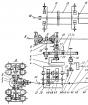
Fig. 9.7. Details of the drum brake mechanism of the rear wheel (showing the parts of the brake mechanism on the left side): 1, 9 - the rods of the support racks of the block; 2 - front shoe of the brake mechanism; 3, 11 - spring plates; 4 - front of the spacer plank; 5 - Top Joint Spring Pads; 6 - working brake cylinder; 7 - the back of the spacer plank; 8 - rear shoe of the brake mechanism; 10 - the expansion lever of the actuator of the parking brake mechanism; 12 - lower chamber spring; 13 - the gap regulator; 14 - gap regulator lever; 15 - Spring Slip Regulator Lever
Replacing worn brake pads with new, do not rush to go right away to lively highways. It is possible that at the first intensive braking you will be unpleasantly affected by the low brake efficiency despite the fact that branded pads are installed. Brake drums (and discs) are also wear out, and new blocks concern them only not to the entire plane, practically not braking. Choose a quiet catch or passage without cars and several times smoothly slow down so that the pads are getting started and began to lay down the entire surface. At the same time, evaluate the efficiency of the brakes.
Try not to brake sharply at least the first 100 km. With a strong heating of the unsurdered pads, the upper layer of their linings is burning and the brakes will not be as effective as efficient as possible.
Replace the brake pads of the rear brake mechanisms only with a set of 4 pcs. (two each way). Before replacing the brake pads, check the level of the brake fluid in the tank of the main brake cylinder. If the level is close to the upper label, it is necessary to pump out part of the fluid, since after replacing the worn pads, the new level will rise.
You will need: screwdrivers with cruciform and flat blade, passage.
1. Include I transmission (translate the automatic transmission selector to the "P" position) and install the counter-packed stops ("shoes") for the front wheels.
2. Loosen the tightening of the rear wheel fastening nuts on the side of the replaceable pads.
3. Raise and install the back of the spring ... car for support. Finally unscrew the fastening nuts and remove the wheel.
Replacing brake pads Hyundai Solaris In a timely manner, it is the guarantee of your safety. Therefore, you should not ignore this procedure. Moreover, such a car repair is almost any driver. Replacing the brake pads on Hyundai Solaris is required as wear, both the pads themselves and brake discs themselves. After all, the wheels themselves change only with the pads.
Hyundai Solaris brake mechanism is equipped with two independent brake systems: working and parking. The first, equipped with hydraulic drive, provides braking when the vehicle moves, the second brakes the car in the parking lot.
The working system is two-kinning, with a diagonal connection of the brake mechanisms of the front and rear wheels. The first hydraulic circuit provides the operation of the right front and left rear brake mechanisms, the second - left front and right rear.
Brake mechanism front wheels Hyundai Solaris disc, with automatic adjustment of the gap between the pads and a disk with a movable bracket. On the mobile bracket, a single-passive working brake cylinder is installed. The guide pad is attached by two bolts to a swivel fist. The movable bracket is attached by bolts to the guide fingers installed in the holes of the guide pads. The guide fingers are lubricated with grease and protected by rubber covers. In the cavity of the cylinder of the mobile bracket, a piston with a sealing ring is installed. Due to the elasticity of this ring, the optimal gap between the pads and the ventilated disk is maintained, the surface of which is protected by the brake shield. The full process of replacing the front pads of Hyundai Solaris is looking at this page.
To the question when to change brake pads Hyundai Solaris, Answer can give special acoustic indicators standing on the pads. Simply put on the pads are metal plates "Foods", which begin to make a nasty sound when braking, if the block thickness approaches the critical level.
Circular brake mechanism rear wheels Hyundai Solaris It has a similar design as the front brakes. The brake pads are powered by one hydraulic working cylinder. The optimal gap between the disk and the pads is supported by the same principle as the brake mechanisms of the front wheels. In addition, the rear brakes still perform the additional feature of the parking brake (handbrake).
Parking brake Hyundai Solaris It is driven mechanically. A constructive parking brake consists of a lever installed on the body base between the front seats, the front cable with the adjustment device and the equalizer to which two cables are attached, and the levers installed in the brake mechanisms of the rear wheels. The parking brake does not require much care. When lifting the handbrake, the cable is tensioned and the brake piston press the rear pads to the disk. Detailed instructions for replacing the rear pads Hyundai Solaris.
It is worth noting that the front pads wear much more intense than the rear, therefore require more frequent replacement.
Brake amplifier
Your car is equipped with a brake system with an amplifier, automatically adjusted in the process of normal operation.
If there will be a loss of power in the brake system with an amplifier as a result of a spontaneous stop of the engine or for any other reason, you can still stop the car, applying a greater effort to brake pedal than usual. The braking path, however, will increase.
If the engine does not work, then the braking force will be sequentially reduced each time the brake pedal is pressed. Do not "download" a brake pedal if the effect of the brake enhancement system is broken.
You can "download" a pedal of brakes only if necessary to maintain a car control on a slippery road.
CAUTION
- Brake system
Do not keep your leg on brake pedals while driving. This will lead to an unacceptable high heating of brakes, excessive wear of brake linings and pads, as well as to an increase in the braking path.
On the length and steep descent, turn on lower transmission and avoid long-term brakes. Prolonged the use of brakes will lead to overheating and may eventually cause the temporary loss of the braking force.
Moisturizing brakes can lead to the fact that the car will not be able to slow down as usual and it will "take away" to the side when they are braked. It is possible to determine the degree of influence of this effect on the braking characteristics by small test braking. Always check in this way the brakes work after overcoming the deep fusion. To dry the brakes, slightly turn them on while moving forward at a safe speed until the restoration of normal braking characteristics.
Always before moving from the place. Check the position of the brake pedal and accelerator.
If you have not checked the position of the accelerator pedal and brake before moving from the place, you can press the accelerator pedal instead of the brake pedal. This can lead to a serious accident.
In case of brake failure
In case of failure of working brakes during the movement of the car, you can emergency to stop using the parking brake. The braking path, however, will be much longer than usual.
CAUTION
The use of parking brakes while moving with normal speed can lead to a sudden loss of car control. If you have to use the parking brake to stop the car, be extremely careful.
Disk brake wear indicator
On your car installed disc brakes.
With the wear of the brake pads and the need for their replacement will be heard a warning sound of high tone from the front or rear brakes (if available). This sound can appear and disappear, or distributed at each press of the brake pedal.
Remember that under certain road conditions or climate, the first braking (or slow motion) may be accompanied by a brake squeal. This is a normal phenomenon, and is not a sign of a brake malfunction.
ATTENTION
To avoid expensive brake repair, do not keep moving with worn brake pads.
Always replace the brake pads included for the wheels of the front or rear axle.
CAUTION
- wear brakes
This warning signal of brake wear indicates the need to repair the car. Neggrerying this sound warning will lead to the loss of the efficiency of the braking system, which, in turn, can cause a serious road accident.

- Electronic Stabilization System (ESP) Stabilization System (if available)
- Work of the Electronic Stability Stabilization System (ESP)
Other online:
Dropping pressure in the supply system of gasoline engines
Remember that gasoline is highly flammable liquid! When working with power system components, observe all the received fire safety measures. Do not smoke! Do not close to the month ...
Camshaft. The axis of the camshaft
1. Remove the axis of a bruise and rocker (p. 2.8). 2. Remove the slave pulley of the camshaft (p. 2.6.14-2.6.16). 3. Remove the camshaft from the cylinder head towards the flywheel. Shaft thoroughly ...
Removing and installing the lock of the lid lid fuel tank and drive
You will need: all the tools needed to withdraw the rear cladding of the left threshold of the floor and the trunk cladding, as well as the end head "on 10". 1. Remove the front and rear cladding of the left ...
Hyundai Solyaris Brake System
Hyundai Solaris Brake System
Brake system: 1 - ABS block; 2 - hydraulic tank; 3 - main brake cylinder; 4 is the brake fluid level sensor; 5 - vacuum amplifier; 6 - Tubes of the main brake cylinder.
The working brake system is a hydraulic, dual-circuit, with a diagonal separation of contours, which increases the safety of the vehicle operation. One of the circuits of the working brake system ensures the operation of the brake mechanisms of the left front and right rear wheels, and the other - right front and left rear wheels.
In normal mode, when the system is working, both contours work.
When refusing (depressurizing), one of the contours of another circuit provides car braking, albeit with less efficiency. The working brake system includes brake mechanisms of wheels, a pedal assembly, a vacuum amplifier, a main brake cylinder, a hydraulic cylinder tank, an ABS block, and connective tubes and hoses.
Brake pedal - suspended type.
 Pedal knot
In the bracket of the pedal node, the brake pedal position sensor is installed, combined with a braking signals switch - its contacts are closed when the brake pedal is pressed. The sensor displays a signal of the ECU that the brake pedal is pressed. The vacuum brake amplifier is designed to reduce the effort that needs to be attached to the brake pedal when car braking, due to the use of the vacuum in the intake pipeline of the engine. The amplifier is located between the brake pedal and the main brake cylinder and is attached to four nuts to the bracket of the pedal node. The vacuum amplifier is unbearable, when you fail, it is replaced with a new one.

The main brake cylinder is attached to the vacuum enhancer body with two nuts. From above on the cylinder installed a shared tank of the hydraulic system of the brake system and the clutch, in which the supply of liquid is located. On the tank body, the maximum and minimum fluid levels are applied. A fluid level sensor is installed in the tank, which, when lowering the liquid level, below the MIN mark includes a signaling device in a combination of instruments.
When you press the brake pedal, the pistons of the main cylinder are moved by creating pressure in the hydraulic engine, which is supplied through the tubes and hoses to the working cylinders of the brake mechanisms of the wheels.
The brake mechanism of the front wheel is a disk, with a floating caliper, which includes a single-surface wheeled cylinder.
For more efficient cooling, the brake disc is performed ventilated.
Brake mechanisms of the left and right front wheels are non-violent.

Brake Front Wheel Mechanism

On the caliper of the left brake mechanism there is marked L. on the caliper of the right brake mechanism - marking R.

Support front brake mechanism assembly with guide and pads
The guide of the brake pad is attached to the twilty fist, and the caliper is attached to two bolts to the guide fingers installed in the holes of the guide pads. Protective covers installed on the fingers. When braking, the fluid pressure in the hydraulic engine of the brake mechanism increases and the piston, putting forward from the wheel cylinder, made in one integer with the caliper, presses the inner brake block to the disk. The caliper is then (due to the movement of the guide fingers in the holes of the guide pad) shifts relative to the disk, pressing the outer brake block to it. In the cylinder case, a piston with a sealing rubber ring is installed.

Elements of the front wheel brake mechanism: 1 - guide pads; 2 - outer brake shoe; 3 - guide plate; 4 - protective cover of the guide finger; 5 - upper guide finger; 6 - Caliper with a working cylinder; 7 - bolt fixing the caliper to the guide finger; 8 - lower guide finger; 9 - internal brake block.
Due to the elasticity of this ring between disk and blocks of the brake mechanism, a constant optimal clearance is maintained (the optimal clearance is supported in the rear disk brake mechanism).

A acoustic wear indicator is attached to the inner brake pad and the anti-belly plate is fastened, which also protects the brake cylinder boof.
Depending on the configuration on cars, two types of brake mechanisms of the rear wheels can be installed: disk or drum.

Circular brake rear wheel mechanism by car: 1 - ABS sensor; 2 - brake hose; 3 - parking brake cable; 4 - return spring of the parking brake mechanism; 5 - protective cap of pumping fitting; 6 - guide finger; 7 - protective cover of the guide finger; 8 - Caliper with a working cylinder; 9 - brake disc.

Elements of the disc brake mechanism of the rear wheel: 1 - guide pads; 2 - outer brake shoe; 3 - guide plate; 4 - protective cover of the guide finger; 5 - upper guide finger; 6 - Caliper with a working cylinder; 7 - bolt fixing the caliper to the guide finger; 8 - lower guide finger; 9 - internal brake shoe with acoustic wear indicator.

Parking brake drive on the caliper: 1 - lever; 2 - return spring; 3 - threaded rod
The disc brake mechanism of the rear wheel - with a floating caliper, which includes a single-passive working cylinder.

Rear Wheel Brake Mechanism Caliper
The design of the rear brake cylinder is very complex, since it combines a conventional hydraulic cylinder in itself (similar to the design with the front brake cylinder) and the mechanism of the parking brake. The parking brake drive works as follows. The parking brake cable acts on the actuator lever and turns it. In the original position, the drive lever returns the spring.
Thus, the movement of the lever is transmitted to the threaded rod, which interacts with the threaded finger installed in the piston.

Threaded Cylinder Caliper
The threaded finger can turn into the piston. Moreover, when the finger pressed against the inner surface of the piston, then turning is very difficult, and if the finger leaves from the piston, it turns easily on the stubborn bearing.
The threaded finger in the piston presses (through the thrust bearing) of the spring. Thus, as the brake pads wear, the threaded finger is further disulfed from the threaded rod, allowing the piston to exit the cylinder and at the same time maintain the constant course of the parking brake.
 Piston with a threaded finger
Such a design of the rear brake cylinder and determines the method of blending the piston into the cylinder when replacing the pad.
The piston can not just push into the cylinder.
The use of great effort will damage the details.
The piston must be turned clockwise and simultaneously pressing hard on it to ensure proper friction and screwing the threaded finger into the threaded stock of the parking brake drive.
The guide pad is attached to the rear suspension lever.
The pads of disk brake mechanisms of the front and rear wheels differ in the design.

The drum brake mechanism of the rear wheel (for clarity is shown with a wheel hub): 1 - rear brake shoe; 2 - bracket of the support rack; 3 - reference rack; 4 - parking brake drive lever; 5 - spacer plank; 6 - upper blast spring; 7 - working (wheel) cylinder; 8 - ratchet; 9 - adjustment lever; 10 - Spring of the adjusting lever; 11 - front brake shoe; 12 - brake shield; 13 - Lower Spring; 14 - Spring of the parking brake cable.
The drum braking mechanism is with a two-star wheeled cylinder, two brake pads with automatic adjustment of the gap between the pads and the drum.
The mechanism of automatic adjustment begins to work with an increase in the gap between the pads and the brake drum. When you press the brake pedal, the blocks begin to diverge and cuddle to the brake drum, while the protrusion of the adjusting lever moves along the depression between the keshes of the ratchet. With a certain wear of the pad and pressing the brake pedal, the adjusting lever is enough to turn the ratchet to one tooth, thereby increasing the length of the spacer plate and at the same time reducing the gap between the pads and the drum. So gradual extension of the spacer automatically maintains the gap between the brake drum and the pads. The wheel cylinders of the brake mechanisms of the rear wheels are the same. The front blocks of brake mechanisms are the same, and the rear differences are (on them the mirror-symmetrically installed non-removable levers of parking brakes).

Elements of the mechanism of automatic adjustment of the gap between the pads and the drum: A - the brake mechanism of the left wheel; b - brake mechanism of the right wheel; 1 - spacer plank; 2 - ratchet; 3 - tip of the spacer plank; 4 - adjusting lever
The spacer plate and the left-wheel brake mechanism ratchet have a silver color (on the rod of the ratchet and in the hole of the spacer plate, the left thread is made), and the right wheel is a golden color (on the rod of the ratchet and in the opening of the spacer plank, the right thread is made). On the cylindrical ends of the ratchets, the tips of the spacer schedules are equal for the brake mechanisms of the left and right wheels. Adjustable levers of the left and right wheels mirror-symmetrical.

Parking brake lever: 1 - parking brake lever; 2 - the operating room switch of the parking brake; 3 - adjusting nut; 4 - front line of parking brake; 5 - equalizer.
The parking brake lever, fixed between the front seats on the floor tunnel, is connected to two cables through the front cable and the equalizer. Rear cable tips are connected to the levers of the parking brake drive, fixed on the rear brake calipers (disk mechanism) or on the rear brake pads (drum mechanism). Adjusting the parking brake is carried out by rotating the adjusting nut, located on the front cable tip.
Cars are equipped with anti-lock brake systems (ABS).
The brake fluid from the main brake cylinder enters the ABS block, and from it to the brake mechanisms of all wheels.

ABS unit: 1 - control unit; 2 - hole for connecting the tube of the brake mechanism of the right front wheel; 3 - hole for connecting the tube of the left rear wheelhole; 4 - hole for connecting the tube of the brake mechanism of the right rear wheel; 5 - hole for connecting the tube of the left front wheel brake mechanism; 6 - hole for connecting the tube of the main brake cylinder; 7 - pump; 8 - hydraulic modulator.
The ABS block, fixed in the engine compartment on the left side member, under a vacuum amplifier, consists of a hydraulic modulator, pump and control unit.
ABS acts depending on wheel speed sensor signals. Sensors - inductive type.

Front and rear wheel speed sensors
The front wheel rotation speed sensor is installed in the hole of the swivel fist and is fixed by a bolt. The sensor's defined disk is pressed on the exterior casing. The rear wheel speed of the rear wheel speed is installed in the rear suspension beam flange flange and is also fixed by a bolt. The sensor defining disc is installed in the rear wheel hub (the hub node is intimidate).
When braking the car, the ABS control unit determines the start of the wheel lock and opens the appropriate modulator solenoid valve to reset the pressure fluid pressure in the channel.
The valve opens and closes several times per second, so make sure that ABS works, it is possible on a weak trembling of brake pedal at the time of braking.
The ABS is built in the brake force distribution system (EBD), which performs the function of the pressure regulator in the hydraulic drive of the brake mechanisms of the rear wheels. If when braking a car, the rear wheels begin to be blocked, the inlet valves of the brake mechanisms of the rear wheels in the modulator are switched to the main pressure maintenance mode, preventing further increase in pressure in the rear brake operating cylinders.
If a malfunction occurs in ABS, the brake system retains performance, but it is possible to block the wheels. In this case, the corresponding fault code is recorded in the control unit memory, which is read with the help of special equipment in the service center.
Hyundai Solyaris Brake System
Site navigation
Expand | Turn
Complexity
Without toolsNot indicated
Period: week month
For 30 days:
For 7 days:
Viewing duration:
Watch now:
average rating
Estimate the article
Good (4 bala)
Without tools
All operations can be performed by hand without a tool.
Not indicated
Average time
Working brake system - hydraulic, double-circuit, with a diagonal separation of contours, which increases the safety of the car. One of the circuits of the working brake system ensures the operation of the brake mechanisms of the left front and right rear wheels, and the other - right front and left rear wheels.
In normal mode, when the system is working, both contours work.
When refusing (depressurizing), one of the contours of another circuit provides car braking, albeit with less efficiency. The working brake system includes brake mechanisms of wheels, a pedal assembly, a vacuum amplifier, a main brake cylinder, a hydraulic cylinder tank, an ABS block, and connective tubes and hoses.

Brake system elements:
1 - ABS block;
2 - hydraulic tank;
3 - main brake cylinder;
4 - the brake fluid level sensor;
5 - vacuum amplifier;
6 - Tubes of the main brake cylinder.
In the bracket of the pedal node, the brake pedal position sensor is installed, combined with a braking signals switch - its contacts are closed when the brake pedal is pressed. The sensor displays a signal of the ECU that the brake pedal is pressed. The vacuum brake amplifier is designed to reduce the effort that needs to be attached to the brake pedal when car braking, due to the use of the vacuum in the intake pipeline of the engine. The amplifier is located between the brake pedal and the main brake cylinder and is attached to four nuts to the bracket of the pedal node. The vacuum amplifier is unbearable, when you fail, it is replaced with a new one.

Brake pedal node.
The main brake cylinder is attached to the vacuum enhancer body with two nuts. From above on the cylinder installed a shared tank of the hydraulic system of the brake system and the clutch, in which the supply of liquid is located. On the tank body, the maximum and minimum fluid levels are applied. A fluid level sensor is installed in the tank, which, when lowering the liquid level, below the MIN mark includes a signaling device in a combination of instruments.
When you press the brake pedal, the pistons of the main cylinder are moved by creating pressure in the hydraulic engine, which is supplied through the tubes and hoses to the working cylinders of the brake mechanisms of the wheels.

The main brake cylinder.
Brake Front Wheel Mechanism - disk, with floating caliper, including a single-surface wheeled cylinder.
For more efficient cooling, the brake disc is performed ventilated.
Brake mechanisms of the left and right front wheels are non-violent.

Brake mechanism of the front wheel.
On the caliper of the left brake mechanism there is marked L. on the caliper of the right brake mechanism - marking R.

Marking on brake mechanisms calipers.

Support front brake mechanism assembly with guide and pads.
The guide of the brake pad is attached to the twilty fist, and the caliper is attached to two bolts to the guide fingers installed in the holes of the guide pads. Protective covers installed on the fingers. When braking, the fluid pressure in the hydraulic engine of the brake mechanism increases and the piston, putting forward from the wheel cylinder, made in one integer with the caliper, presses the inner brake block to the disk. The caliper is then (due to the movement of the guide fingers in the holes of the guide pad) shifts relative to the disk, pressing the outer brake block to it. In the cylinder case, a piston with a sealing rubber ring is installed. Due to the elasticity of this ring between disk and blocks of the brake mechanism, a constant optimal clearance is maintained (the optimal clearance is supported in the rear disk brake mechanism).

Front wheel brake mechanism elements:
1 - guide pads;
2 - outer brake shoe;
3 - guide plate;
4
5 - upper guide finger;
6
7
8 - lower guide finger;
9 - Inner brake shoe.
A acoustic wear indicator is attached to the inner brake pad and the anti-belly plate is fastened, which also protects the brake cylinder boof.

Brake Pad Elements:
1 - anti-billion plate brake pads;
2 - Acoustic brake pad wear indicator.
Depending on the configuration on cars, two types of brake mechanisms of the rear wheels can be installed: disk or drum.

1 - ABS sensor;
2 - brake hose;
3 - Parking brake cable;
4 - Return spring of the parking brake mechanism;
5 - protective cap of pumping fitting;
6 - guide finger;
7 - protective cover of the guide finger;
8 - Caliper with a working cylinder;
9 - brake disk.

The elements of the disc brake mechanism of the rear wheel:
1 - guide pads;
2 - outer brake shoe;
3 - guide plate;
4 - protective cover of the guide finger;
5 - upper guide finger;
6 - Caliper with a working cylinder;
7 - bolt fixing the caliper to the finger guide;
8 - lower guide finger;
9 - Inner brake shoe with acoustic wear indicator.

Parking brake drive elements on the caliper:
1 - lever arm;
2 - Return spring;
3 - Threaded rod.
Circular brake rear wheel mechanism - with a floating caliper, which includes a single-minded working cylinder.

Caliper brake mechanism rear wheel.
The design of the rear brake cylinder is very complex, since it combines a conventional hydraulic cylinder in itself (similar to the design with the front brake cylinder) and the mechanism of the parking brake. The parking brake drive works as follows. The parking brake cable acts on the actuator lever and turns it. In the original position, the drive lever returns the spring.
Thus, the movement of the lever is transmitted to the threaded rod, which interacts with the threaded finger installed in the piston.

Threaded rod in caliper cylinder.
The threaded finger can turn into the piston. Moreover, when the finger pressed against the inner surface of the piston, then turning is very difficult, and if the finger leaves from the piston, it turns easily on the stubborn bearing.
The threaded finger in the piston presses (through the thrust bearing) of the spring. Thus, as the brake pads wear, the threaded finger is further disulfed from the threaded rod, allowing the piston to exit the cylinder and at the same time maintain the constant course of the parking brake.
Such a design of the rear brake cylinder and determines the method of blending the piston into the cylinder when replacing the pad.
The piston can not just push into the cylinder.
The use of great effort will damage the details.
The piston must be turned clockwise and simultaneously pressing hard on it to ensure proper friction and screwing the threaded finger into the threaded stock of the parking brake drive.
The guide pad is attached to the rear suspension lever.
The pads of disk brake mechanisms of the front and rear wheels differ in the design.

Piston with a threaded finger.
Drum brake mechanism- with a two-star wheeled cylinder, two brake pads with automatic clearance adjustment between pads and drum.

The rear wheel drum brake mechanism (for clarity is shown with the wheel hub):
1 - rear brake shoe;
2 - bracket of support rack;
3 - reference rack;
4 - parking brake lever;
5 - spacer plank;
6 - upper blast spring;
7 - a worker (wheel) cylinder;
8 - ratchet;
9 - adjusting lever;
10 - Spring adjustment lever;
11 - front brake shoe;
12 - brake shield;
13 - lower chamber spring;
14 - Spring the cable of the parking brake.
The mechanism of automatic adjustment begins to work with an increase in the gap between the pads and the brake drum. When you press the brake pedal, the blocks begin to diverge and cuddle to the brake drum, while the protrusion of the adjusting lever moves along the depression between the keshes of the ratchet. With a certain wear of the pad and pressing the brake pedal, the adjusting lever is enough to turn the ratchet to one tooth, thereby increasing the length of the spacer plate and at the same time reducing the gap between the pads and the drum. So gradual extension of the spacer automatically maintains the gap between the brake drum and the pads. The wheel cylinders of the brake mechanisms of the rear wheels are the same. The front blocks of brake mechanisms are the same, and the rear differences are (on them the mirror-symmetrically installed non-removable levers of parking brakes).
The spacer plate and the left-wheel brake mechanism ratchet have a silver color (on the rod of the ratchet and in the hole of the spacer plate, the left thread is made), and the right wheel is a golden color (on the rod of the ratchet and in the opening of the spacer plank, the right thread is made). On the cylindrical ends of the ratchets, the tips of the spacer schedules are equal for the brake mechanisms of the left and right wheels. Adjustable levers of the left and right wheels mirror-symmetrical.

Elements of the mechanism of automatic adjustment of the gap between the pads and the drum:
but- brake mechanism of the left wheel;
b.- the brake mechanism of the right wheel;
1 - spacer plank;
2 - ratchet;
3 - tip of the spacer;
4 - Adjusting lever.
The parking brake lever, fixed between the front seats on the floor tunnel, is connected to two cables through the front cable and the equalizer. Rear cable tips are connected to the levers of the parking brake drive, fixed on the rear brake calipers (disk mechanism) or on the rear brake pads (drum mechanism). Adjusting the parking brake is carried out by rotating the adjusting nut, located on the front cable tip.

Parking brake lever elements:
1 - parking brake lever;
2 - Parking brake signaling switch;
3 - adjusting nut;
4 - front cable of parking brake;
5 - equalizer.
Cars are equipped with anti-lock brake systems (ABS).
The brake fluid from the main brake cylinder enters the ABS block, and from it to the brake mechanisms of all wheels.
The ABS block, fixed in the engine compartment on the left side member, under a vacuum amplifier, consists of a hydraulic modulator, pump and control unit.
ABS acts depending on wheel speed sensor signals.
When braking the car, the ABS control unit determines the start of the wheel lock and opens the appropriate modulator solenoid valve to reset the pressure fluid pressure in the channel.
The valve opens and closes several times per second, so make sure that ABS works, it is possible on a weak trembling of brake pedal at the time of braking.
The ABS is built in the brake force distribution system (EBD), which performs the function of the pressure regulator in the hydraulic drive of the brake mechanisms of the rear wheels. If when braking a car, the rear wheels begin to be blocked, the inlet valves of the brake mechanisms of the rear wheels in the modulator are switched to the main pressure maintenance mode, preventing further increase in pressure in the rear brake operating cylinders.
If a malfunction occurs in ABS, the brake system retains performance, but it is possible to block the wheels. In this case, the corresponding fault code is recorded in the control unit memory, which is read with the help of special equipment in the service center.

Block elements ABS:
1 - Control block;
2 - a hole for connecting the tube of the brake mechanism of the right front wheel;
3 - hole for connecting the tube of the left rear wheelhole;
4 - hole for connecting the tube of the brake mechanism of the right rear wheel;
5 - hole for connecting the tube of the left front wheel brake mechanism;
6 - hole for connecting the tube of the main brake cylinder;
7 - pump;
8 - hydraulic modulator.
The front wheel rotation speed sensor is installed in the hole of the swivel fist and is fixed by a bolt. The sensor defining disk is pressed on the exterior casing. Rear wheel speed sensor is mounted in the rear suspension beam lever flange hole and is also fixed by a bolt. The sensor defining disc is installed in the rear wheel hub (the hub node is intimidate).

Rear wheel speed sensors.

Front wheels rotation speed sensors.
The article lacks:
- Quality photo repair