How the CAN bus works. Using the CAN tire: how to programmatically control the car
Tire CAN-Bus. It was created in the late 80s by Robert Bosch GmbH (Germany) as a solution for distributed systems operating in real time. A distinctive feature Tires is her high noise immunity. An additional advantage of the CAN bus is its resistance to mechanical damage - the closure of the tire conductors to the shared wire, the power or interconnects does not lead to the failure of the devices. Moreover, some tire modifications are capable of functioning when one of the conductors is broken.
CAN bus in industrial networks
The CAN (Controller Area Network) field tire is characterized by high data transfer and noise immunity, as well as the ability to detect any errors. Thanks to this CAN today is widely used in areas such as automotive and railway transport, Industrial Automation, Aviation, Access and Control Systems. According to the CIA Association (CAN IN Automation, www.can-cia.de), about 300 million CAN nodes around the world are currently in operation. In Germany, CAN-tire ranks first in popularity among other field tires.
CAN Protocol Features Benefits CAN
The overall trend in the field of automation is to replace the traditional centralized management system for distributed control by placing intelligent sensors and actuators next to the controlled process. This is caused by an increase in the number of communication wires, an increase in the number of compounds, the complexity of the diagnosis of errors and problems with reliability. The connection between the nodes of such a system is carried out using the fieldbus. CAN is a communication system for multi-terminol systems. Consider in more detail the advantages of CAN and the reasons for which CAN is becoming increasingly distributed.
Tested standard. The CAN protocol is actively used for more than 20 years, which is very important for such conservative areas as railway transport or shipbuilding. CAN was designed in 1980 by Robert Bosch for the automotive industry. The CAN interface is regulated by international standards ISO 11898 for high-speed and ISO 11519-1 for low-speed applications. Low cost is determined by a good price / performance ratio, also the wide availability of CAN controllers on the market. Reliability is determined by the linear structure of the tire and the equality of its nodes, the so-called multimaptation (MULTI MASTER Bus), in which each CAN node can access the bus. Any message can be sent to one or more nodes. All nodes are simultaneously read from the bus and the same information, and each of them decides, take this message or ignore it. Simultaneous reception is very important for synchronization in control systems. Refused nodes are disconnected from the bus exchange.
High noise immunity is achieved due to the suppression of the sphaseous interference with a differential transceiver, the operation of embedded error detection mechanisms (one unnecessary error for 1000 years at the daily 8-hour operation of the network at a speed of 500 kbps), the reference of the erroneous messages, disconnect the faulty nodes from the bus and stability To electromagnetic interference.
Flexibility is achieved due to a simple connection to the bus and disconnect from the CAN node bus, and the total number of nodes is not limited to the lower level protocol. Address information is contained in the message and combined with its priority, according to which arbitration is carried out. In the process of work it is possible to change the priority of the transmitted message. It should also be noted the possibility of programming the frequency and phase of the transmitted signal and arbitration, which does not destroy the structure of conflict messages. At the physical level, there is the ability to select a different data transfer lines: from cheap twisted pair to fiber optic communication line.
Real-time work becomes possible thanks to network interaction mechanisms (multimaptation, broadcasting, broken arbitration) in combination with a high data transfer rate (up to 1 Mbps), a rapid response to a transmission request and a variable message length from 0 to 8 bytes.
CAN applications
CAN is an ideal solution for any application where microcontrollers are exchanged by messages with each other and with remote peripheral devices. Initially, CAN was used in cars to ensure a critical control time and exchange time between the engine and the gearbox when the message is guaranteed the message and tolerance of each of the network participants to work with current data. Along with fairly expensive high-speed solutions, there are both cost-effective solutions for connecting to the network of inertial devices that work in the time scale of hundreds of microseconds (door control system, window lift, mirror control). At the same time powerful harnesses electric wires Replaced with a two-wire CAN network, whose nodes are, including brake lights and rotation indicators.
CAN has found wide use in industrial automation, where there is a large number of control devices, sensors, mechanisms, electric drives and other objects that are associated with a single technological cycle (heating and air conditioning systems, pumps, conveyors, elevators, escalators, conveyors, etc.) . An important feature of such systems is the ability to diagnose and manage objects located on a large area, according to adaptive algorithms. As a result, a significant reduction in power consumption, noise, equipment wear is achieved. Such a picture is observed in railway onboard systems, where the crucial role is played by the exchange of data between subsystems when setting speed, braking, controlling the doors and diagnostics.
Physical level
The physical level of the CAN bus is the connection "assembly and" between all devices connected to it. Differential signaling lines are called CAN_H and CAN_L and in static condition are under the potential of 2.5 V. Log. 1 (recessive bit) indicates the tire state at which the level on the CAN_H line is higher than the CAN_L level. With log. 0 (dominant bit) level on the CAN_H line is lower than the level of CAN_L. The following tire status agreement is adopted: the passive state of the tire corresponds to the log level. 1, and active - log level. 0. When messages are not transmitted over the tire, it is in passive state. Message transmission always starts with a dominant bit. The logic of the tire works corresponds to "wired and": the dominant bit "0" suppresses the recessive bit "1" (Fig. 12.1).
Fig. 12.1. CAN Tire Work Logic
With the physical implementation of a specific project with CAN, it is necessary to determine the properties of the bus and its nodes: where processing devices are located, what properties they have, what sensors and actuators are present in the system, they are intellectual or not, which can be said about their physical location. Depending on the operating conditions, a single-wire line can be used (within the printed circuit board), two-wire line, twisted pair or fiber optic line. With a differential method of generating signals, a two-wire line allows to significantly increase noise immunity. When using differential stresses, the CAN network continues to function in an extremely noisy environment or when one of the signal lines is broken. Even with a simple twisted pair, the differential inputs can effectively neutralize noise.
The maximum data transfer rate is 1 Mbps with a bus length of 40 m and about 40 kbps with a bus length of 1000 m.
CAN varieties
Currently, various devices with CAN interface are available, which in addition to transmitting data from one point to another allow you to implement synchronization of processes and maintenance of priorities. Earlier implementations of CAN controllers use frames with a 11-bit identifier and the possibility of addressing up to 2048 messages and comply with CAN Specifications V. 2.0A. Such controllers are called Basic CAN and are characterized by a strong workload of the central processor (CPU), since each incoming message is remembered in memory and the CPU decides, it is necessary for the message data or not (Fig. 12.2). Basic CAN controllers contain one transmit buffer and one or two receiving message buffers. To send or receive a message, it is required to use the CPU through the interrupts "message_locked" and "message_name". As a result of checking each incoming message, the CPU load is very large, which limits the actual exchange rate over the network. For this reason, such controllers are used in CAN networks with low exchange rate and / or small number of messages.

Fig. 12.2. Structure of the Basic CAN controller
Most CAN controllers produced today use advanced messages with an identifier of 29 digits long, which allows you to address up to 536 million messages. Such controllers comply with CAN V. 2.0B specification (Active) and are called Full-CAN controllers. They provide a buffer for several messages, and each message has its own mask, and the filtering is carried out by matching the mask identifier.
In the case of Full-CAN, the CPU is unloaded as possible because it does not handle unnecessary messages (Fig. 12.3). When receiving messages with the identifier corresponding to the mask, it is remembered in the special zone of the two-port RAM, and the operation of the CPU is interrupted. Full-Can also has special type Messages that means: "Whatever this information is, please send it now." The Full-CAN controller automatically listens all messages and sends the requested information.

Fig. 12.3. Full-Can Controller Structure
Until recently, the industry was widespread Basic CAN with a 11-bit identifier. This protocol admits a simple bond between microcontrollers and peripheral devices at the exchange rate up to 250 kbps. However, with the rapid reduction of CAN controllers, the use of Full-Can has become justified and for communication with slow devices. If the industrial applications require high-speed (up to 1 Mbps) data exchange, then Full-CAN should be used.
CAN-Tire Arbitrage
CAN has many unique properties that distinguish it from other tires. The CAN protocol takes place to send messages over a common CAN bus, while there are no sender's addresses and a message recipient. Each node constantly "browsing" the tire and performs local filtering when receiving, using bit masks, and decides which messages to retrieve from the tire.
As a result, the node receives and processes only those messages that are intended for it.
Each message has its own priority, the value of which is contained in the message identifier. In addition, identifiers are used to indicate the message type. Message with the younger identifier number corresponds to the highest priority; The highest priority has a message with an identifier consisting entirely of zeros. Message Transmission begins with sending an identifier to the bus. If access to the bus requires multiple messages, the message with the highest priority will be transferred to the highest priority, that is, with a smaller identifier value, regardless of other messages and the current status of the tire. Each node before passing the message checks whether a node works with a higher priority. If so, it returns to the receiver state and tries to transfer the message to another time. This property is of particular importance when used in real-time control systems, since the priority value rigidly determines the waiting time.
If the transmission of the node A is suspended by a node B, sending a message with a higher priority, as soon as the bus is released, another attempt to send a message from the node A. This principle was named CSMA / CA: Carrier Sense Multiple Access / Collision Avoidance (shared access with polling / conflict prevention). This mode, unlike Ethernet, does not allow conflicting nodes in the bus to find out the relationship, and immediately identifies the winner and reduces the exchange time.
So, thanks to the arbitration of the tire, the message with the highest priority is transmitted first, ensuring the functioning of the system in real time and the rapid transmission of information. The distribution of priorities between different types of messages is specified by the developer when designing the network.
Message format
If you do not consider the repetimate procedure taken with an error, there are two types of communication between nodes: one node transmits information, and the other receives, or the A node A requests the data node b and receives the answer.
Fig. 12.4. Data frame (Data Frame)
For data transfer serves as a data frame - Data Frame. (Fig. 12.4), which contains:
- the identifier indicating the message type ("Speed_digator", "Temperature_Masla") and on the priority of access to the bus. The identifier field contains a different number of bits depending on the variety of the protocol: in the standard CAN V2.0A format there is a 11-bit identifier, and in the extended CAN V2.0B - 29-bit;
- the data field containing the appropriate message ("Speed_digator" \u003d 6000 rpm, "temperature_masla" \u003d 110 ° C) up to eight bytes;
- two bytes of the checksum - CYCLIC REDUNDANCY CHECK (CRC) To identify and correct the transfer errors.
To query information, the CAN node uses the Remote Frame data request frame (Fig. 12.5), which contains:
- identifier defining the type of information requested ("engine speed", "temperature_masla") and message priority;
- two bytes checksum CRC..
Fig. 12.5. Remote Frame Data Request Frame
In this case, the identifier does not follow the data and the data length code does not have a direct relation to the number of data bytes. The node that is suggested to transfer the information (oil temperature sensor) transmits a data frame containing the required information. Thus, if the node A directs the node into the request frame with the "temperature_masla" identifier, the node in the temperature sensor and directs the node and the data frame containing the "Masla temperature" identifier and the required information.
Additional InformationThe frame contained in the frame allows you to determine the format and synchronization of the message transfer protocol and the type of parcel:
- what message is sent - a data request or actual data determines the bit of remote transmission request (RTR for a 11-bit identifier and SRR for 29-bit);
- data length code reporting how many data bytes contains a message; All nodes take the data frame, but those of them that this information is not needed is not preserved;
- to synchronize and control the frame contains start fields Start of Frame, End of Frame End of Frame and Acknowledgment Field Confirmation;
- the input to the synchronization mode on the bus is performed by the first bit of the Start of Frame field, then synchronization is supported by the front when changing the level of sent bits;
- bitstafing mechanism is used - inserting an additional bit at the following in a row five zeros or units.
Error detection
Error alarm occurs by transmitting Error Frame error frame. It is initiated by any node that found a mistake. CAN controllers use the method of statistical error processing. Each node contains error meters when transmitting and receiving Transmit Error Counter and Receive Error Counter. If the transmitter or receiver detect the error, the value of the corresponding counter increases. When the counter value exceeds a certain limit, the current transmission is interrupted. The node issues an error signal in the form of an Error Frame, where an active dominant error flag is 6 bits. After that, the node, the transfer of which was interrupted, repeats the message. Unreliable or partially damaged nodes allowed to send only a passive recessive flag of error.
In CAN there are several varieties of errors. Of these, three types at the level of messages:
- CRC ERROR is a checksum error (when the CRC received in the CRC field and calculated checksums).
- Form Error is a frame format error when the received message received by the CAN format.
- ACKNOWLEDGEMENT ERROR - message reception confirmation error, if none of the nodes confirmed correctly received the message.
In addition, there are two types of bike bugs:
- Bit Error is the detection of the active divergence assembly between the level sent to the bus and the actual value due to the implementation of the node of the self-monitoring mechanism.
- STUFF ERROR - the presence in the message field of the six next in a row bit 0 or 1 (bitstafing error).
Thanks to these error detection and correcting mechanisms, the likelihood of error skipping is extremely small. For example, at a speed of 500 kbps, a bus load of 25% and use for 2000 hours per year there is only one unnecessary error in 1000 years. In addition, the tire is impossible to block a defective node of the entire network. Such nodes are detected and disconnected from the bus exchange.
CAN bus - IntroductionCAN protocol is an ISO standard (ISO 11898) in the sequential data transmission area. The protocol was developed with an eye on use in transport applications. Today CAN got widespread and is used in industrial automation systems, as well as in transport.
The CAN standard consists of a physical layer and data level that defines several different types of messages, the rules for resolving conflicts when accessing the bus and protection against failures.
CAN protocol
The CAN protocol is described in ISO 11898-1 and may be briefly described as follows:
The physical level uses differential data transmission over twisted pair;
To control the access to the bus uses non-destructive BIT-WISE conflict resolution;
Messages have small sizes (for the most part 8 bytes of data) and are protected by the checksum;
There are no explicit addresses in messages, instead, each message contains a numeric value that manages its sequence on the bus, and can also serve as the identifier of the message content;
A well-thought-out error handling scheme that re-transmit messages if they were not obtained properly;
Available effective means To insulate the failures and delete failed nodes from the bus.
Switches of higher levels
The CAN protocol itself determines only as small data packets can be safely moved from point A to point B by means of a communication medium. He, as expected, says nothing about how to control the stream; transmit a large amount of data than it is placed in an 8-byte message; any addresses of nodes; establishing a compound, etc. These items are determined by a higher level protocol (HLP). The term HLP comes from the OSI model and its seven levels.
Higher-level protocols are used for:
Standardization of the launch procedure, including the selection of data transfer rate;
Distribution of addresses among interacting nodes or types of messages;
Defining message markup;
Provide error proceedings at the system level.
Custom groups, etc.
One of the most effective ways to improve your competence in the CAN is to participate in the work carried out within the framework of existing user groups. Even if you do not plan to actively participate in work, user groups can be a good source of information. A visit to the conference is another good way obtain comprehensive and accurate information.
CAN products
At a low level, the two types of CAN products available on the open market - CAN chips and CAN development tools are fundamentally distinguished. At a higher level - other two types of products: CAN modules and CAN design tools. A wide range of these products is available on the open market now.
CAN patents
Patents related to CAN applications can be of various types: Implementing synchronization and frequencies, transmitting large data sets (in the CAN protocol, data frames are only 8 bytes long), etc.
Distributed control systems
CAN protocol is a good basis for developing distributed control systems. The conflict resolution method used by CAN provides that each CAN node will interact with those messages that belong to this node.
The distributed control system can be described as a system whose computing power is distributed between all the system nodes. The opposite option is a system with a central processor and local I / O points.
CAN messages
CAN tire refers to broadcast bus. This means that all nodes can "listen" all the programs. There is no possibility to send a message to a specific node, all the nodes will take all messages without exception. CAN Equipment, however, provides the possibility of local filtering, so that each module can only respond to its message.
CAN messages addressing
CAN uses relatively short messages - the maximum length of the information field is 94 bits. There are no explicit addresses in messages, they can be called content-addressed: the contents of the message implicitly (implicitly) determines the addressee.
Types of messages
There are 4 types of messages (or frames) transmitted by the CAN bus:
Data frame (DATA FRAME);
Remote frame (Remote Frame);
Error Frame Frame;
Overload Frame Frame.
Data frame
Briefly: "Hello everyone, there is data with marking X, I hope you like!"
The data frame is the most common message type. It contains the following main parts (some details are not considered for brevity):
Arbitration field (Arbitration Field), which defines the message order in the case when two or more nodes are struggling. The arbitration field contains:
In the case of CAN 2.0A, a 11-bit identifier and one bit, the RTR bit that is defining for data frames.
In the case of CAN 2.0B, a 29-bit identifier (which also contains two recessive bits: SRR and IDE) and the RTR bit.
Data field (Data field), which contains from 0 to 8 bytes of data.
The CRC field (CRC Field) containing a 15-bit checksum calculated for most parts of the message. This checksum is used to detect errors.
Recognition Slot (Acknowledge Slot). Each CAN controller, capable of getting correctly received, sends the recognition bit (Acknowledgement BIT) at the end of each message. The transceiver checks the presence of the recognition bit and, if so, is not detected, it sends the message again.
Note 1: The presence on the tire of the bit of recognition does not mean anything except that each scheduled addressee received a message. The only thing that becomes is known is the fact of correct receipt of the message with one or more bus nodes.
Note 2: The identifier in the arbitration field, despite its name, optionally identifies the contents of the message.
CD 2.0B data frame (Standard CAN).

CD 2.0B data frame (Advanced CAN).
Remote frame
Briefly: "Hello everyone, can anyone make data with labeling x?"
The remote frame is very similar to the data frame, but with two important differences:
It is clearly marked as a remote frame (the RTR bit in the field of arbitration is recessive), and
There is no data field.
The main task of the remote frame is the request for the transfer of the proper data frame. If, let's say, the node A is sent to a remote frame with an arbitration field parameter equal to 234, then node B, if it is properly initialized, must be sent in response to the data frame with the field of the arbitration field also equal to 234.
Remote frames can be used to implement the query-response tire traffic management. In practice, however, a remote frame is used little. It is not so important because the CAN standard does not prescribe act as indicated here. Most CAN controllers can be programmed so that they will automatically respond to a remote frame, or instead to notify the local processor.
There is one trick associated with remote frame: Data length code (Data Length Code) must be set to the length of the expected response message. Otherwise, the resolution of conflicts will not work.
Sometimes it is required that the node responding to the remote frame starts its transfer as soon as recognized the identifier, thus "filling" an empty remote frame. This is another case.

Error Frame Frame
Briefly (all together, loud): "Oh, dear, let's try another time"
Error Frame Frame is a special message that violates the rules for forming frames of the CAN message. It is sent when the node detects a failure and helps the rest of the nodes to detect a failure - and they will also send erachnog boxes. The transmitter will automatically try to send a message again. There is a thoughtful error meter diagram, which guarantees that the node cannot disrupt data transmission over the bus by repeating references of the error frames.
The error frame contains an error flag (Error Flag), which consists of 6 bits of the same value (thus violate the bits insertion rule) and error delimiter (Error Delimiter) consisting of 8 recessive bits. An error runtime provides some space in which other bus nodes can send their error flags after the first error flag itself will detect.

Overload Frame Frame
Brief: "I am very busy 82526 small, could you wait a minute?"
The overload frame is mentioned here only for completeness of the picture. In the format, it is very similar to the frame of the error and is transmitted by a busy node. The overload frame is used infrequently, because Modern CAN controllers are quite productive to not use it. In fact, the only controller that will generate overload frames is now outdated 82526.
Standard and advanced CAN
Initially, the CAN standard set the identifier in the arbitration field to be 11 bits. Later, at the request of buyers, the standard was expanded. The new format is often called the extended CAN (Extended CAN), it allows you to use at least 29 bits in the identifier. To distinguish between two types of frames, a reserved batch is used in the Control Field control field.
Formally, standards are referred to as follows -
2.0a - only with 11-bit identifiers;
2.0B - an extended version with 29-bit or 11-bit identifiers (they can be mixed). Node 2.0b can be
2.0B Active (active), i.e. able to transmit and receive extended shots, or
2.0B Passive (passive), i.e. It will be silently discharged enhanced personnel (but, see below).
1.x - refers to the original specification and its audits.
Currently, new CAN controllers usually refer to type 2.0b. 1.x or 2.0a type controller will arrive in confusion, receiving messages with 29 bits of arbitration. The passive type controller 2.0b will accept them, identifies if they are true and, then - will reset; A Active type controller 2.0B will be able to transmit and receive such messages.
Controllers 2.0B and 2.0a (equal, as and 1.x) are compatible. You can use them all on one bus until the 2.0b controllers will refrain from sending extended frames.
Sometimes people say that the standard CAN "Better" extended CAN, because in the extended CAN messages more service data. This is optional so. If you use the data arbitration field, the extended CAN frame may contain less service data than standard CAN frame.
Main CAN (Basic CAN) and Full CAN (Full CAN)
Terms Basic Can and Full Can originate in the "childhood" CAN. Intel 82526 CAN controller existed, providing a programmer interface in DPRAM style. Then Philips appeared with the 82C200 model, which uses a FIFO-oriented programming model and limited opportunities filtration. To refer to the difference between the two programming models, people began to call the Intel - Full CAN method, and the Philips - Basic CAN method. Today, most CAN controllers support both programming models, therefore it makes no sense to use Full CAN and Basic CAN terms - in fact, these terms can be confusing and it is worth refraining from their use.
In fact, the Full CAN controller can interact with the Basic CAN controller and vice versa. There are no compatibility issues.
Conflict resolution on tire and message priority
Resolution of conflicts of messages (process, as a result of which two or more CAN controllers decide who will use the bus) is very important to determine the real availability of bandwidth for data transmission.
Any CAN controller can start a transmission when it detects that the bus is idle. This may lead to the fact that two or more controllers will begin the transmission of the message (almost) at the same time. The conflict is solved as follows. Transmitting nodes monitor bus during the sending process. If the node detects the dominant level at a time, he himself sends a recessive level, it will immediately eliminate the conflict resolution process and will become a receiver. Conflict resolution is carried out throughout the entire field of arbitration, and after this field is sent, only one transmitter remains on the tire. This node will continue to transmit if nothing happens. The remaining potential transmitters will try to transfer their messages later when the tire is free. In the process of resolution of the conflict, the time is not lost.
An important condition for a safe resolution of the conflict is the impossibility of a situation in which two nodes can transmit the same field of arbitration. From this rule there is one exception: if the message does not contain data, any node can transmit this message.
Since the CAN bus is a bus with a connection to the "Mounting and" type devices (Dominant BIT) and the dominant bit (Dominant Bit) is a logical 0, therefore a message with the lowest arbitration field in the numerical expression will benefit in the conflict resolution.
Question: What happens if the only tire node tries to send a message?
Answer: The node, of course, will win in resolving the conflict and will successfully conduct the transfer of the message. But when the recognition time comes ... No node will send a dominant bit of recognition area, so the transmitter determines the recognition error, the error flag will increase the value of its 8 error counter to 8 and start re-transmitting. This cycle will repeat 16 times, then the transmitter will switch to the status of a passive error. In accordance with the special rule in the error limit algorithm, the transmission error counter will not be more increased if the node has a passive error status and an error is the recognition error. Therefore, the node will carry out the transmission forever, until someone recognizes the message.
Addressing and Identification Messages
Repeat, there is nothing terrible in the fact that there are no accurate addresses in CAN messages. Each CAN controller will receive all tire traffic, and using a combination of hardware filters and software, to determine - "interests" his message, or not.
In fact, the concept of the message address is missing in the CAN protocol. Instead, the contents of the message are determined by the identifier that is somewhere in the message. CAN messages can be called "Contentive Address".
The specific address is working like this: "This is a message for node X". The content-addressed message can be described as follows: "This message contains data with marking X". The difference between these two concepts is small, but essential.
The contents of the arbitration field is used, in accordance with the standard, to determine the sequence of the message on the bus. All CAN controllers will also use everything (some - only part) the arbitration field as a key in the hardware filtering process.
Standard does not say that the arbitration field must certainly be used as a message identifier. However, this is a very common use option.
Note on identifier values
We said that the identifier is available 11 (CAN 2.0A) or 29 (CAN 2.0B) bits. This is not entirely true. For compatibility with a specific old CAN controller (guess what?), Identifiers should not have 7 senior bits installed in a logical unit, so the 11-bit identifiers are available values \u200b\u200b0..2031, and users of 29-bit identifiers can use 532676608 different values.
Note that all other CAN controllers accept "wrong" identifiers, so in modern systems CAN Identifiers 2032..2047 can be used without restrictions.
Physical levels CAN.
Tire Can.
CAN bus uses the code without returning to zero (NRZ) with bits insert. There are two different states of the signal: dominant (logic 0) and recessive (logical 1). They correspond to certain electrical levels depending on the physical layer used (several of them). Modules are connected to the bus according to the "Installation and" (Wired-and "scheme: if at least one node translates the bus to the dominant state, then the entire tire is in this state, out of the dependence on how many nodes are transmitted by recessive state.
Various physical levels
Physical level Specifies the electrical levels and the signal transmission circuit over the tire, the total resistance of the cable, etc.
There are several different versions of physical levels: the most common is a variant defined by the CAN standard, part of ISO 11898-2, and is a two-wire balanced signal circuit. It is also sometimes called High Speed \u200b\u200bCan.
Another part of the same ISO 11898-3 standard describes another two-wire balanced signal circuit - for less high-speed bus. It is resistant to failures, so the transmission of signals can continue even when one of the wires are cut, closed on the "land" or in a VBAT state. Sometimes such a scheme is called Low-Speed \u200b\u200bCAN.
SAE J2411 describes the single-wire (plus the "Earth", of course) the physical level. It is used mainly in vehicles - for example GM-LAN.
There are several proprietary physical levels.
In the former times, when CAN drivers did not exist, the modifications of RS485 were used.
Various physical levels usually cannot interact with each other. Some combinations can work (or it will seem that they work) in good conditions. For example, High-Speed \u200b\u200band Low-Speed \u200b\u200btransceivers can operate on one bus only sometimes.
The absolute majority of CAN transceiver chips are produced by Philips; Other manufacturers include Bosch, Infineon, Siliconix and Unitrode.
The most common transceiver 82C250, which implements the physical level described by the ISO 11898 standard. Improved version - 82C251.
A common transceiver for "Low-Speed \u200b\u200bCan" - Philips TJA1054.
Maximum data transfer rate over bus
Maximum data transfer rate on CAN bus, In accordance with the standard, equal to 1 Mbps. However, some CAN controllers maintain speeds above 1 Mbps and can be used in specialized applications.
LOW-SPEED CAN (ISO 11898-3, see above) runs at speeds up to 125 kbps.
Single-wire CAN bus in standard mode can transmit data at a speed of about 50 kbps, and in a special high-speed mode, for example, for programming the ECU (ECU), about 100 kbps.
Minimum data transfer rate over bus
Keep in mind that some transceivers will not allow you to choose a speed below a certain value. For example, when using 82C250 or 82C251, you can easily set the speed of 10 kbps, but if you are using TJA1050, you cannot set the speed below 50 kbps. Check with the specification.
Maximum cable length
With a data rate of 1 Mbps, the maximum length of the cable used may be about 40 meters. This is due to the requirement of the conflict resolution scheme, according to which the wave front of the signal should be able to reach the far node and return before the bit be read. In other words, the length of the cable is limited to the speed of light. Proposals for increasing the speed of light were considered, but were rejected in connection with intergalactic problems.
Other maximum cable lengths (approximate values):
100 meters at 500 kbps;
200 meters at 250 kbps;
500 meters at 125 kbps;
6 kilometers at 10 kbps.
If optocars are used to ensure electroplating isolation, the maximum tire length is appropriately reduced. Tip: Use quick optocouplers, and look at the signal delay in the device, and not on maximum speed Data transfer to specification.
Tire termination
ISO 11898 CAN Standard CAN bus must end with the terminator. This is achieved by installing a 120 ohm resistance resistor at each end of the tire. Termination serves two goals:
1. Remove the signal reflection at the end of the tire.
2. Ensure that the correct DC levels (DC) receives.
The CAN Tire of the ISO 11898 standard must be terminated regardless of its speed. I will repeat: the CAN bus of the ISO 11898 standard must be terminated regardless of its speed. For laboratory work it may be enough for one terminator. If your CAN tire works even in the absence of terminators - you are just lucky.
Note that other physical levels, such as Low-Speed \u200b\u200bCAN, single-wire bus CAN and others may require, and may not require the presence of a tire terminator. But your high-speed CAN bus standard ISO 11898 will always require at least one terminator.
Cable
The ISO 11898 standard prescribes that the wave resistance of the cable nominally should be 120 ohms, but the interval of the resistance values \u200b\u200bof Ohm is allowed.
Few, from those present in the market today, cables satisfy these requirements. There is a high probability that the interval of resistance values \u200b\u200bwill be expanded in the future.
ISO 11898 describes a twisted pair shielded or unshielded. It is working on the SAE J2411 single-wire cable standard.
Electric chains of cars became complicated and smasted from year to year. The first cars did without a generator and battery - the ignition worked from Magneto, and the headlights were acetylene.
By the mid-70s, hundreds of meters of electrical wires were linked to the harnesses, cars for electrical equipment, compete with light motor aircraft.
The idea of \u200b\u200bsimplifying wiring lay on the surface - it would be nice to pave only one wire in the car, drive consumers on it and put a certain control device near each. Then the energy for consumers (light bulbs, sensors, executive devices) and control signals could be used along this wire.
By the beginning of the 90s, the development of digital technologies made it possible to start implementing this idea - Bosch and Intel companies were developed by the CAN network interface for creating on-board multiprocessor real-time systems. In electronics, the wired system for which the data is transmitted is called "tire".
If the data is transmitted along two wires (so-called "twisted pair") sequentially, the pulse behind the pulse is a serial bus (Serial Bus), if the data is transmitted from several wires at the same time - it will be a parallel bus (Parallel Bus).
And although the parallel bus works faster, it does not suit it to simplify the wiring of the car - it just complicates it. Twisted pair of sequential tire is capable of transmitting to 1Mbps, which is quite enough.
The rules for which individual blocks exchange information are called the protocol in electronics. The protocol allows you to send individual commands to individual blocks, interview each unit individually or all at once. In addition to address access to devices, the Protocol provides for the possibility of setting priorities to the commands themselves. For example, the engine management team will have priority before the air conditioner command.
The development and miniaturization of electronics can now produce low-cost management and communication modules, which in the car can be connected as stars, rings or chains.
The exchange of information is in both directions, i.e. You can not only turn on for example light bulb rear strokeBut it also shines if it shines.
Having information from various devices, the engine control system will select the optimal mode, the air conditioning system will turn on heating or cooling, the wiper control system will be brushed and the like.
The system of engine diagnostics and the entire car as a whole is greatly simplified.
And although the main dream of an electrician is just two wires all over the car - has not yet come true, CAN tire has significantly simplified the wiring of the car and raised the overall reliability of the entire system.
So, the CAN bus is a digital communication and control system electrical devices A car that allows you to collect data from all devices, share information between them, manage them. Information on the status of devices and command (control) signals for them are transmitted in digital form on a special protocol with two wires, so-called. "Twisted pair." In addition, the power supply from the onboard power grid is supplied to each device, but unlike conventional wiring - all consumers are connected in parallel, because No need to lead from each switch to each light bulb its wire. This greatly simplifies the installation, reduces the number of wires in the harness and increases the reliability of the entire electrical system.
The number of installed sensors on modern car models often allows you to call them "computers on wheels." In order to put in order to control numerous electronic systems, a CAN bus was created. What is it and what the principles of its work, consider in this article.
Historical reference
The first products of the automotive industry were carried out at all without electrical chains. To start the car engine, a special magnetoelectric device generated electricity from kinetic was used.
However, gradually the cars were increasingly let off with wires, and in the 1970s in the degree of stuffing various sensors they roldled with airplanes. And the more appliances were placed in the car, the more apparently the need to rationalize the electrical wiring chains.
The solution to the problem became possible with the microprocessor revolution and took place in several stages:
- In 1983. german concern Bosch began developing a new data transfer protocol for use in the automotive industry;
- Three years later, at a conference in Detroit, this protocol was officially represented by the general public called the "Sensor Space Network", or abbreviated in English CAN;
- The practical implementation of the German invention was engaged in Intel and Philips. The first prototypes are dated 1987;
- In 1988. car BMW The 8th series became the first car that came from the conveyor, in which all sensors were organized by the "Kan" technology;
- Three years later, Bosch updated the standard and added new characteristics;
- In 1993, the standard "Kan" became international and received the ISO classifier;
- In 2001, every four-wheeled vehicle in Europe was necessarily equipped with a can-bus;
- In 2012 came out a new version Tires: The speed of information transfer was raised, and also organized compatibility with a number of new devices.

CAN-tire: work principle
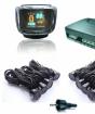
The tire includes only a pair of wires connected to a single microchip. For each cable, several hundred signals are transmitted simultaneously to various car controllers. Data transfer rate is comparable to broadband Internet. In addition, if necessary, the signal will be strengthened to the required level.
Technology work can be divided into several stages:
- Background mode - All system nodes are turned off, but power supply continues to the can-microchip. The level of energy consumption is extremely small and is the tiny shares of Milliamper;
- Running - As soon as the driver turns the ignition key (or presses the "Start" button to start the engine - on some models of cars), the system literally "wakes up". The power stabilization mode arriving on the sensors is turned on;
- Active work - All controllers are exchanged necessary (both diagnostic and current) information. The level of electricity consumption increases on peak loads to a record 85 milliamm;
- Floating - As soon as the engine is turned off, the "Kan" sensors instantly stop working. Each of the system nodes is independently disconnected from the electrical network and goes into sleep mode.

What is a CAN bus in the car?
CAN as applied to the car can be called a "ridge" to which all electrical devices are connected. The signals have a digital format, and the conductors to each controller are connected in parallel. Thanks to this, high speed network is achieved.
In modern cars, sensors from the following devices are combined into a single network:
- Motor;
- Gear box;
- Eirbagi (airbags);
- Anti-lock system;
- Steering amplifier;
- Ignition;
- Dashboard;
- Tires (controllers defining the level of pressure);
- "Janitors" on the windshield;
- Multimedia system;
- Navigation (GLONASS, GPS);
- On-board computer.

Application in other industries
The ease and simplicity of CAN technology disclose its use not only for " iron horses" The tire is also used in such areas:
- Bicycle production. Japanese Mark. "Simano" announced a bike in 2009 with a multi-level control system for switching speeds on the CAN. The effectiveness of this step was so obvious that in the footsteps "Simano" decided to go other firms - "Marantz" and Bayon-X. " The latest manufacturer uses a bus for a direct drive system;
- The implementation of the so-called "smart home" on the principle of CAN-tire is known. Many devices that can solve certain tasks without people's participation (automatic watering on the lawn, thermostat, video surveillance system, lighting control, climate control, etc.) are combined into unified system data transmission. True, experts find the use of purely automotive technology in human dwelling quite dubious. Among weak Parties Such a step is the lack of a single international standard Kan for "smart homes".

Advantages and disadvantages
"CAN-TIN" is valued in mechanical engineering for such positive qualities:
- Speed: The system is adapted to work under hard cement conditions;
- Relative ease of embedding in the car and a small level of maintenance costs;
- Increased tolerance to interference;
- Multi-level control system that avoids many errors in the data logging process;
- The scatter of operation speeds allows you to adapt to almost any situation;
- Increased level of safety: blocking unauthorized access from the outside;
- Mature standards, as well as manufacturers. The palette of the tires available on the market allows you to find an option even for the cheapest car.
Despite the abundance of advantages, CAN technology is not deprived of a number of weaknesses:
- The amount of information that is available for simultaneous transmission to the "data packet" is sufficiently limited for modern requirements;
- A significant part of the data transmitted has a service and technical purpose. On proper useful data accounts for a meager part of the network traffic;
- Protocol higher Level Not standardized.
The company "Bosch" invented not only the spark plug and fuel filterBut also a kind of "Internet" for the car sensors called the CAN bus. What is this standard in the field of binding together all controllers in a single neural networkIt became known about 30 years ago.

Video: How can CAN bus in auto
In this video, the mechanic Arthur Camalaan will tell, for which the CAN bus is used in the car and how to connect to it:
CAN bus is electronic devicebuilt into the electronic car system for control specifications and driving performance. It is a mandatory element for equipping the car with an anti-theft system, but it is only a small part of its capabilities.
CAN bus is one of the devices in the electronic automation of the car, which is covered by the task of combining various sensors and processors into the overall synchronized system. It provides a collection and exchange of data, whereby the necessary adjustments are made to the operation of various systems and nodes of the machine.
CAN abbreviation is decrypted as Controller Area Network, that is, a network of controllers. Accordingly, the CAN bus is a device that receives information from devices and transmitting between them. This standard was developed and implemented more than 30 years ago by Robert Bosch GmbH. It is now used in the automotive industry, industrial automation and the design of objects designated by "smart", such as houses.
How can Can bus
In fact, the tire is a compact device with a multitude of inputs for connecting cables or connector to which cables are connected. The principle of its action lies in the transfer of messages between different components of the electronic system.
An identifiers are included in the messages to send different information. They are unique and reported, for example, that at a specific point in time, the car rides at a speed of 60 km / h. The message series is sent to all devices, but thanks to individual identifiers, they only handle those that are intended for them. CAN-tire identifiers can have a length of 11 to 29 bits.
Depending on the purpose of the Kov, the tires are divided into several categories:
- Power. They are designed to synchronize and exchange data between electronic block Engine and anti-lock system, gearbox, ignition, other car work units.
- Comfort. These tires ensure the joint operation of digital interfaces that are not associated with the driving blocks of the machine, and are responsible for comfort. This is a seats heating system, climate control, mirror adjustment, etc.
- Informational commanders. These models are designed to operate information between nodes responsible for maintenance of the car. For example, navigation system, smartphone and computer.
Why can Can bus in the car
The distribution of the CAN interface in the automotive sphere is due to the fact that it performs a number of important functions:
- simplifies the algorithm for connecting and functioning additional systems and devices;
- reduces the effect of external interference to the operation of electronics;
- provides simultaneous receipt, analysis and transmission of information to devices;
- accelerates the transmission of signals to mechanisms, chassis and other devices;
- reduces the number of required wires;
IN modern car The digital bus ensures the operation of the following components and systems:
- central mounting block and ignition castle;
- anti-lock system;
- engine and gearbox shift;
- airbags;
- steering gear;
- steering rotation sensor;
- force aggregate;
- electronic blocks for parking and locking doors;
- pressure sensor in wheels;
- wind control unit;
- high pressure fuel pump;
- sound system;
- informational navigation modules.
This is not a complete list, since it does not include external compatible devices, which can also be connected to the bus. Often the automotive alarm is often connected. CAN bus is also available for connecting external devices to monitor operating performance and diagnostics on a PC. And when connecting car alarm, together with the Lighthouse, you can control individual systems from outside, for example, from a smartphone.
Pros and Can Bus Tire
Specialists in the automotive electronics, expressing in favor of using the CAN interface, mark the following advantages:
- simple data exchange channel;
- information transfer rate;
- wide compatibility with working and diagnostic devices;
- more simple scheme auto alarm installations;
- multi-level monitoring and monitoring interfaces;
- automatic distribution of the transmission rate with priority in favor of the main systems and nodes.
But there are CAN-tires and functional disadvantages:
- with an increased information load on the channel, the response time grows, which is especially characteristic of cars, "stuffed" by electronic devices;
- due to the use of the highest level protocol, standardization problems are found.
Possible problems with CAN bus
Due to the inclusion in many functional processes, the CAN-bus problems are manifested very quickly. Among the signs of violations most often appear:
- indication of the question mark on the dashboard;
- simultaneous luminescence of several light bulbs, such as Check Engine and ABS;
- the disappearance of the fuel level indicators, engine speed, speed on the dashboard.
Such problems occur for various reasons associated with power or disruption of electrocups. It may be closing a mass or battery, breaking the chain, damage to the jumpers, the voltage drop due to problems with the generator or the discharge of the AKB.
The first measure for checking the tire is a computer diagnostics of all systems. If it shows the bus, it is necessary to measure the voltage at the outputs H and L (should be ~ 4V) and study the signal shape on an ignition oscilloscope. If there is no signal or it corresponds to the voltage of the network, there is a closure or a break.
Due to the complexity of the system and a large number of connections computer diagnostic And troubleshooting is advisable to pass into the hands of specialists with high-quality equipment.