Gas-dynamic processes in the engine silencer. Mashkur Mahmoud A.
Probably, it is worth talking more about the exhaust systems of DVS in general to learn how to divide "flies from the kitlet" in this not easy to understand the area. Not easy from the point of view of physical processes occurring in the muffler after the engine has already completed another worker, and, it would seem, did his job.
Then it will be about model two-stroke enginesBut all reasoning is true for four-strokes, and for the engines "non-model" cubatures.
Let me remind you that far from each exhaust tract of DVS, even built according to the resonant diagram, can give an increase in power or engine torque, as well as reduce its noise level. By and large, these are two mutually exclusive requirements, and the design task exhaust system It is usually reduced to the search for a compromise between the noise of DVS, and its power in one or another mode of operation.
This is due to several factors. Consider the "ideal" engine, in which the internal loss of energy for friction of sliding nodes is zero. We will also not take into account the losses in rolling bearings and loss, inevitable when internal gas-dynamic processes (suction and purge). As a result, all the energy released during combustion fuel mixeswill be spent on:
1) the useful work of the model drivers (propeller, wheel, etc. It is not possible to consider the efficiency of these nodes, it is a separate topic).
2) Losses arising from another cyclical phase of the process of work of the DVS - exhaust.
It is the loss of exhaust worth considering in more detail. I emphasize that it is not about the work stroke tact (we agreed that the engine "inside itself is ideal), but about the" ejecting "losses of the combustion of the fuel mixture from the engine into the atmosphere. They are determined mainly, the dynamic resistance of the exhaust path itself is the whole thing that joins the motor of the motor. From the entrance to the outlet holes of the "silencer". I hope you do not need to convince anyone that the smaller the resistance of the channels, according to which the gases from the engine are "departed", the less you will have to spend the efforts on it, and the faster the process of "gas separation" will pass.
Obviously, it is the phase of the exhaust of the internal combustion system that is the main in the process of noise formation (forget about the noise arising during suction and the burning of fuel in the cylinder, as well as about mechanical noise from the operation of the mechanism - the perfect MEX mechanical noise can simply be). It is logical to assume that in this approximation, the total efficiency of the DVS will be determined by the relationship between the useful work, and the loss of exhaust. Accordingly, the reduction in the exhaust loss will increase the efficiency of the engine.
Where is the energy lost when the exhaust is spent? Naturally, it is converted into acoustic oscillations. ambient (atmosphere), i.e. In noise (of course, there is also a heating of the surrounding space, but we still default about it). The place of occurrence of this noise is a cut of an exhaust window of the engine, where there is a jump-like expansion of exhaust gases, which initiates acoustic waves. The physics of this process is very simple: at the time of opening the exhaust window in a small volume of the cylinder there is a large portion of compressed gaseous residues of fuel combustion products, which when entering the surrounding space is quickly and sharply expanded, and a gas-dynamic blow occurs, provoking subsequent floating acoustic oscillations in the air (Remember the cotton arising from the scolding of a bottle of champagne). To reduce this cotton, it is enough to increase the expiration time of compressed gases from the cylinder (bottle), limiting the cross section of the exhaust window (smoothly opening the plug). But this method of reducing noise is not acceptable for a real engine, which, as we know, power directly depends on the revolutions, therefore - from the speed of all flowing processes.
You can reduce the noise of the exhaust in another way: do not limit the cross-sectional area of \u200b\u200bthe exhaust window and the expiration time exhaust gasesBut limit the speed of their expansion is already in the atmosphere. And this method was found.
Back in the 30s of the last century, sports motorcycles and cars began to equip peculiar conical exhaust pipes With a small opening corner. These silencers were called "MegaFones". They slightly reduced the level of exhaust noise of the engine, and in some cases, it was also reduced, to increase the power of the engine due to improving the cleaning of the cylinder from the remnants of the spent gases due to the inertia of the gas pillage moving inside the conical exhaust pipe.
Calculations and practical experiments have shown that the optimal angle of the megaphone is close to 12-15 degrees. In principle, if you make a megaphone with such an angle of revealed very long, it will effectively extinguish the engine noise, almost without reducing its capacity, but in practice such structures are not implemented due to obvious design deficiencies and restrictions.
Another way to reduce the noise of DVS is to minimize pulsations of exhaust gases at the output of the exhaust system. For this, the exhaust is made not directly into the atmosphere, and in an intermediate receiver of sufficient volume (ideally, at least 20 times higher than the working volume of the cylinder), with subsequent release of gases through a relatively small hole, the area of \u200b\u200bwhich can be several times less than the exhaust area window. Such systems smooth the pulsating nature of the movement of the gas mixture at the outlet of the engine, turning it into close to the uniform-progressive at the outlet of the muffler.
Let me remind you that the speech at the moment goes about the devastating systems that do not increasing gas-dynamic resistance to exhaust gases. Therefore, I will not concern all sorts of tricks of the type of metal grids inside the devastating chamber, perforated partitions and pipes, which, of course, allow you to reduce the noise of the engine, but to the detriment of its power.
The next step in the development of silencers was systems consisting of various combinations of the methods described above. I will say right away, for the most part they are far from ideal, because In one degree or another, the gas-dynamic resistance of the exhaust path increases, which uniquely leads to a decrease in the power of the engine transmitted to the propulsion.
//
Page: (1)
2 3 4 ... 6 "
The gas-dynamic supervision includes methods for increasing the charge density at the inlet by use:
· The kinetic energy of air moving on the receiving device in which it is converted to the potential pressure of pressure when braking the stream - high-speed supervision;
· Wave processes in intake pipelines -.
In the thermodynamic cycle of the engine without boosting the beginning of the compression process occurs at pressure p. 0, (equal atmospheric). In the thermodynamic cycle of the piston engine with a gas-dynamic supervision, the beginning of the compression process occurs at pressure p K. , due to the increase in the pressure of the working fluid outside the cylinder from p. 0 BE p K.. This is due to the transformation of the kinetic energy and the energy of the wave processes outside the cylinder into the potential energy of pressure.
One of the energy sources to increase the pressure at the beginning of the compression may be the energy of the incident air flow, which takes place when the aircraft, car, etc. means. Accordingly, adding in these cases is called high-speed.
High-speed supervision Based on aerodynamic patterns of transformation of high-speed air flow in static pressure. Structurally, it is realized as a diffuser air intake nozzle, aimed at towing air flow when driving vehicle. Theoretically increase the pressure Δ p K.=p K. - p. 0 Depends on speed c. H and density ρ 0 incident (moving) air flow
High-speed supervision finds use mainly on aircraft with piston engines and sports carswhere speed speeds are more than 200 km / h (56 m / s).
The following varieties of gas-dynamic supervision of engines are based on the use of inertial and wave processes in the engine inlet system.
Inertial or dynamic reducing takes place at relatively high speed of moving fresh charge in the pipeline c. Tr. In this case, equation (2.1) takes
where ξ t is a coefficient that takes into account the resistance to the movement of gas in length and local.
Real speed c. The gas flow of gas in intake pipelines, in order to avoid elevated aerodynamic losses and deterioration in the filling of cylinders with fresh charge, should not exceed 30 ... 50 m / s.
The frequency of processes in the cylinders piston engines It is the cause of oscillatory dynamic phenomena in gas-air paths. These phenomena can be used to substantially improve the main indicators of engines (liter power and economy.
Inertial processes are always accompanied by wave processes (fluctuations in pressure) arising from the periodic opening and closing of the inlet valves of the gas exchange system, as well as the return-transit movement of the pistons.
At the initial stage of inlet in the inlet nozzle before the valve, a vacuum is created, and the corresponding wave of pouring, reaching the opposite end of the individual inlet pipeline, reflects the compression wave. By selecting the length and passage section of the individual pipeline, you can get the arrival of this wave to the cylinder at the most favorable moment before closing the valve, which will significantly increase the filling factor, and therefore torque M E. Engine.
In fig. 2.1. A diagram of a tuned intake system is shown. Through the inlet pipe, bypassing throttle valveThe air enters the receiving receiver, and the input pipelines of the configured length to each of the four cylinders from it.
In practice, this phenomenon is used in overseas engines (Fig. 2.2), as well as domestic engines for passenger cars with customized individual inlet pipelines (for example, zMZ engines), as well as on a 2h8.5 / 11 diesel engine, a stationary electric generator having one tuned pipeline into two cylinders.
The greatest efficiency of gas-dynamic supervision takes place with long individual pipelines. Advance pressure depends on the coordination of the engine rotation frequency n., pipeline lengths L. Tr and corners
bending the closure of the intake valve (organ) φ A.. These parameters are related addiction
where is the local sound speed; k. \u003d 1.4 - the adiabatic indicator; R. \u003d 0.287 kJ / (kg ∙ hail.); T. - average gas temperature for the pressure period.
Wave and inertial processes can provide a noticeable increase in charge in a cylinder at large valve discoveries or in the form of increasing recharge in compression tact. The implementation of effective gas-dynamic supervision is possible only for a narrow range of engine rotation frequency. The combination of the phases of the gas distribution and the length of the intake pipeline must provide the greatest filling coefficient. Such selection of parameters are called setting the inlet system.It allows you to increase the engine power by 25 ... 30%. To preserve the effectiveness of gas-dynamic supervision in a wider range of rotational frequency crankshaft Can be used various methods, in particular:
· Applying a pipeline with a variable length l. Tr (for example, telescopic);
· Switching from a short pipeline for long;
· Automatic regulation of gas distribution phases, etc.
However, the use of gas-dynamic supervision for engine boost is associated with certain problems. First, it is not always possible to rationally comply with sufficiently extended intake pipelines. It is especially difficult to do for low-speed engines, because with a decrease in the speed of rotation, the length of the adjusted pipelines increases. Secondly, fixed pipeline geometry gives dynamic setting only in some, quite defined range speed \u200b\u200bregime Work.
To ensure the effect in a wide range, smooth or step adjustment The length of the configured path when switching from one speed mode to another. Step control using special valves or turning dampers is considered more reliable and successfully applied in automotive engines Many foreign firms. Most often use control with switching into two customized pipeline lengths (Fig. 2.3).
In the position of the closed flap, the corresponding mode up to 4000 min -1, air supply from the intake receivers of the system is carried out along a long path (see Fig. 2.3). As a result (compared to the base version of the engine without gas-dynamic supervision), the flow of torque curve is improved on an external speed characteristic (at some frequencies from 2500 to 3500 min -1, the torque increases on average by 10 ... 12%). With increasing rotation speed N\u003e 4000 min -1 Feed switches to a short path and this allows you to increase the power N E. on nominal mode by 10%.
There are also more complex all-life systems. For example, designs with pipelines covering a cylindrical receiver with a rotary drum having windows for messages with pipelines (Fig. 2.4). When the cylindrical receiver is rotated, the length of the pipeline is increased and vice versa, when turning clockwise, it decreases. However, the implementation of these methods significantly complicates the engine design and reduces its reliability.
In multi-cylinder engines with conventional pipelines, the efficiency of gas-dynamic supervision is reduced, which is due to the mutual influence of intake processes in various cylinders. In the car engines, intake systems "set up" usually on the maximum torque mode to increase its stock.
The effect of gas-dynamic superior can also be obtained by the corresponding "setting" of the exhaust system. This method finds use on two-stroke engines.
To determine the length L. Tr and inner diameter d. (or passage section) of the adjustable pipeline it is necessary to carry out calculations using numerical methods of gas dynamics describing the non-stationary flow, together with the calculation of the workflow in the cylinder. The criterion is the increase in power,
torque or reducing the specific fuel consumption. These calculations are very complex. More simple methods Definitions L. three d. Based on the results of experimental studies.
As a result of the processing of a large number of experimental data to select internal diameter d. The adjustable pipeline is proposed as follows:
where (μ. F. Y) MAX is the most effective area of \u200b\u200bthe inlet valve slot. Length L. The trifle pipeline can be determined by the formula:
Note that the use of branched tuned systems such as a common pipe - receiver - individual pipes turned out to be very effective in combination with turbocharging.
UDC 621.436
Effect of aerodynamic resistance of intake and exhaust systems of automotive engines on gas exchange processes
L.V. Carpenters, bp Zhilkin, Yu.M. Brodov, N.I. Grigoriev
The paper presents the results of an experimental study of the influence of the aerodynamic resistance of intake and exhaust systems of piston engines to gas exchange processes. The experiments were carried out on the on-line models of single-cylinder engine. Installations and methods for conducting experiments are described. The dependences of the change in the instantaneous speed and pressure of the flow in the gas-air paths of the engine from the corner of the crankshaft rotation are presented. The data was obtained at different intake resistance coefficients and graduation systems and different rotation frequencies of the crankshaft. Based on the data obtained, conclusions were made of the dynamic features of gas exchange processes in the engine under various conditions. It is shown that the use of the noise muffler smoothes the flow ripple and changes the flow characteristics.
Keywords: piston engine, gas exchange processes, process dynamics, speed pulsation and flow pressure, noise muffler.
Introduction
To intake and exhaust systems of piston engines internal combustion A number of requirements are subject to, among which the main reduction in aerodynamic noise and minimal aerodynamic resistance are the main. Both of these indicators are determined in the interconnection of the design of the filter element, inlet silencers and the release, catalytic neutralizers, the presence of a superior (compressor and / or turbocharger), as well as the configuration of intake and exhaust pipelines and the nature of the flow in them. At the same time, there are practically no data on the impact additional elements intake and exhaust systems (filters, silencers, turbocharger) on gas dynamics in them.
This article presents the results of a study of the effect of the aerodynamic resistance of intake and exhaust systems on gas exchange processes in relation to the piston engine of dimension 8.2 / 7.1.
Experimental plants
and data collection system
Studies of the effect of aerodynamic resistance of gas-air systems on gas exchange processes in piston engineers were carried out on the simulation model of the dimension 4.2 / 7.1, driven by rotation asynchronous engineThe frequency of rotation of the crankshaft of which was adjusted in the range n \u003d 600-3000 min1 with an accuracy of ± 0.1%. An experimental installation is described in more detail.
In fig. 1 and 2 show the configurations and geometric sizes of the intake and exhaust path of the experimental installation, as well as the installation location for the measurement of instantaneous
the values \u200b\u200bof the average speed and pressure of the flow of air.
For measurements of instant pressure values \u200b\u200bin the stream (static) in the PC channel, the pressure sensor £ -10 was used by Wika, the speed of which is less than 1 ms. The maximum relative average mean-square pressure measurement error was ± 0.25%.
To determine the instantaneous medium in the section of the air flow channel, the thermoenemometers of the constant temperature of the original design, the sensitive element of which was the nichrome thread with a diameter of 5 μm and a length of 5 mm. The maximum relative average mean-of-mean error of measuring the speed WX was ± 2.9%.
The measurement of the rotational frequency of the crankshaft was carried out using a tachometric meter consisting of a toothed disk fixed on crankshaft Vale, and inductive sensor. The sensor formed a voltage pulse at a frequency proportional to the rotation speed of the shaft. According to these pulses, the frequency of rotation was recorded, the position of the crankshaft (angle f) was determined and the moment of passing the piston of VMT and NMT.
Signals from all sensors entered an analog-to-digital converter and transmitted to a personal computer for further processing.
Before carrying out experiments, a static and dynamic targeting of the measuring system was carried out in general, which showed the speed necessary to study the dynamics of gas-dynamic processes in the inlet and exhaust systems of piston engines. The total average mean-of-mean error of experiments on the effect of the aerodynamic resistance of gas-air systems of DVS Gas exchange processes were ± 3.4%.
Fig. 1. Configuration and geometric sizes of the intake path of the experimental installation: 1 - cylinder head; 2-bubbling pipe; 3 - measuring tube; 4 - thermoanemometer sensors for measuring air flow rate; 5 - Pressure Sensors
Fig. 2. Configuration and geometric dimensions of the exhaust path of the experimental installation: 1 - cylinder head; 2 - working plot - graduation pipe; 3 - pressure sensors; 4 - thermoemometer sensors
The effect of additional elements on the gas dynamics of intake and release processes was studied with different system resistance coefficients. Resistance was created using various intake filters and release. So, as one of them, a standard air automobile filter was used with a resistance coefficient of 7.5. A tissue filter with a resistance coefficient 32 was chosen as another filter element. The resistance coefficient was determined experimentally through static purge in laboratory conditions. Studies were also conducted without filters.
Effect of aerodynamic resistance on the inlet process
In fig. 3 and 4 show the dependences of the air flow rate and PC pressure in the inlet can
le from the angle of rotation of the crankshaft f at different of its rotation frequencies and when using various intake filters.
It has been established that in both cases (with a silencer and without) pulsation of pressure and air flow rates are most expressed at high speed of rotation of the crankshaft. At the same time in the intake canal with the silencer of noise maximum speed Air flow, as it should be expected, less than in the channel without it. Most
m\u003e x, m / s 100
Opening 1 III 1 1 III 7 1 £ * ^ 3 111
Jeeping valve 1 111 II TI. [Zocrytir. . 3.
§ p * ■ -1 * £ l r-
// 11 "s' \\ 11 III 1
540 (r. Gome. P.K.Y. 720 VMT NMT
1 1 Opening -GBepskid-! Valve A l 1 g 1 1 1 closed ^
1 HDC \\. BPCSKNEO valve "x 1 1
| | A j __ 1 \\ __ mj \\ y T -1 1 \\ k / \\ 1 ^ v / \\ / \\ "g) y / \\ / l / l" PC-1 \\ __ V / -
1 1 1 1 1 1 1 | 1 1 ■ ■ 1 1
540 (r. Cyro. P.K.. 720 VMT NMT
Fig. 3. The dependence of the air velocity WX in the intake channel from the angle of rotation of the crankshaft shaft at different frequencies of the rotation of the crankshaft and different filtering elements: a - n \u003d 1500 min-1; B - 3000 min-1. 1 - without a filter; 2 - standard air filter; 3 - fabric filter
Fig. 4. The dependence of the PC pressure in the inlet channel from the angle of rotation of the crankshaft f at different frequencies of rotation of the crankshaft and different filtering elements: a - n \u003d 1500 min-1; B - 3000 min-1. 1 - without a filter; 2 - standard air filter; 3 - fabric filter
it was brightly manifested with high frequencies of rotation of the crankshaft.
After closing the intake valve, the pressure and speed of the air flow in the channel under all conditions do not become equal to zero, and some of their fluctuations are observed (see Fig. 3 and 4), which is also characteristic of the release process (see below). At the same time, the installation of the inlet noise muffler leads to a decrease in pressure pulsations and air flow rates under all conditions both during the intake process and after the intake valve is closed.
Effect of aerodynamic
resistance to the release process
In fig. 5 and 6 shows the dependences of the air flow rate of the WX and the pressure PC in the outlet from the angle of rotation of the crankshaft form at different rotational frequencies and when using various release filters.
The studies were carried out for various frequencies of rotation of the crankshaft (from 600 to 3000 min1) at different overpressure on the release of PI (from 0.5 to 2.0 bar) without a silent noise and if it is presented.
It has been established that in both cases (with the silencer and without) pulsation of the air flow rate, the most brightly manifested at low frequencies of the crankshaft rotation. In this case, the values \u200b\u200bof the maximum air flow rate remain in the exhaust channel with the noise silencer
merilly the same as without it. After closing the exhaust valve, the air flow rate in the channel under all conditions does not become zero, and some speed fluctuations are observed (see Fig. 5), which is characteristic of the inlet process (see above). At the same time, the installation of the noise muffler on the release leads to a significant increase in the pulsations of the air flow rate under all conditions (especially at ry \u003d 2.0 bar) both during the release process and after the exhaust valve is closed.
It should be noted the opposite effect of aerodynamic resistance on the characteristics of the inlet process in the engine, where air filter Pulsation effects in the intake process and after closing the inlet valve were present, but they were clearly faster than without it. In this case, the presence of a filter in the inlet system led to a decrease in the maximum air flow rate and weakening the dynamics of the process, which is consistent well with previously obtained results in the work.
An increase in the aerodynamic resistance of the exhaust system leads to some increase maximum pressures In the process of release, as well as the displacement of peaks for NMT. In this case, it can be noted that the installation of the silencer of the noise of the output leads to a decrease in the pulsations of the pressure of the air flow under all conditions both during the production process and after the exhaust valve is closed.
hY. m / s 118 100 46 16
1 1 to. T «AIA K T 1 Closing of the MPskal Valve
Opening of ipical |<лапана ^ 1 1 А ікТКГ- ~/М" ^ 1
"" "і | y і \\ / ~ ^
540 (P, Grab, P.K.Y. 720 NMT NMT
Fig. 5. The dependence of the air velocity WX in the outlet from the angle of rotation of the crankshaft shaft at different frequencies of the rotation of the crankshaft and different filtering elements: a - n \u003d 1500 min-1; B - 3000 min-1. 1 - without a filter; 2 - standard air filter; 3 - fabric filter
Px. 5pr 0,150
1 1 1 1 1 1 1 1 1 II 1 1 1 II 1 1 L "A 11 1 1 / \\ 1. ', and II 1 1
Opening | Yypzskskaya 1 Іклапана Л7 1 h І _ / 7 / ", g s 1 \\ h Closing of the Bittseast G / CGTї Alan -
c- "1 1 1 1 1 І 1 l l _Л / І І h / 1 1
540 (p, coffin, pk6. 720
Fig. 6. The dependence of the pressure PC in the outlet from the angle of rotation of the crankshaft f at different frequencies of rotation of the crankshaft and different filtering elements: a - n \u003d 1500 min-1; B - 3000 min-1. 1 - without a filter; 2 - standard air filter; 3 - fabric filter
Based on the processing of dependency changes in the flow rate for separate tact, a relative change in the volume flow of air q was calculated through the exhaust channel when the muffler is placed. It has been established that with low overpressure on the release (0.1 MPa), the consumption q in the exhaust system with a silencer is less than in the system without it. At the same time, if at the frequency of rotation of the crankshaft 600 min-1, this difference was approximately 1.5% (which lies within the error), then with n \u003d 3000 min4 this difference reached 23%. It is shown that for high overpressure of 0.2 MPa, the opposite tendency was observed. The volume flow of air through the exhaust channel with the silencer was greater than in the system without it. At the same time, at low frequencies of rotation of the crankshaft, this exceeded was 20%, and with n \u003d 3000 min1 - 5%. According to the authors, such an effect can be explained by some smoothing of the pulsations of the air flow rate in the exhaust system in the presence of a silent noise.
Conclusion
The conducted study showed that the inlet engine of internal combustion is significantly influenced by the aerodynamic resistance of the intake path:
The increase in the resistance of the filter element smoothes the dynamics of the filling process, but at the same time reduces air flow rate, which corresponds to the filling coefficient;
The effect of the filter is enhanced with the increasing rotation frequency of the crankshaft;
The threshold value of the filter resistance coefficient (approximately 50-55), after which its value does not affect the flow rate.
It has been shown that the aerodynamic resistance of the exhaust system also significantly affects the gas-dynamic and consumables of the release process:
Increasing the hydraulic resistance of the exhaust system in the piston DVS leads to an increase in the pulsations of the air flow rate in the exhaust channel;
With low overpressure on the release in the system with a silent noise, there is a decrease in volumetric flow through the exhaust channel, while at high ry - on the contrary, it increases compared to the exhaust system without a silencer.
Thus, the results obtained can be used in engineering practice in order to optimally choose the characteristics of the inlet and outbuilding silencers, which can provide
the influence on the filling of the cylinder of the fresh charge (filling coefficient) and the quality of the cleaning of the engine cylinder from the exhaust gases (the residual gas coefficient) on certain high-speed modes of the work of the piston engine.
Literature
1. Draganov, B.H. Construction of intake and exhaust channels of internal combustion engines / B.Kh. Draganov, MG Kruglov, V. S. Obukhov. - Kiev: Visit School. Head ed, 1987. -175 p.
2. Internal combustion engines. In 3 kN. Kn. 1: Theory of workflows: studies. / V.N. Lou-Kanin, K.A. Morozov, A.S. Khachyan et al.; Ed. V.N. Lukanina. - M.: Higher. Shk., 1995. - 368 p.
3. Champraozs, B.A. Internal combustion engines: theory, modeling and calculation of processes: studies. In the course "Theory of workflows and modeling of processes in internal combustion engines" / B.A. Chamolaoz, M.F. Faraplatov, V.V. Clementev; Ed. Castle Deat. Science of the Russian Federation B.A. Champrazov. - Chelyabinsk: SUURSU, 2010. -382 p.
4. Modern approaches to the creation of diesel engines for passenger cars and small-calm
zovikov /a. Blinov, P.A. Golubev, Yu.E. Dragan et al.; Ed. V. S. Peponova and A. M. Mineyev. - M.: NIC "Engineer", 2000. - 332 p.
5. Experimental study of gas-dynamic processes in the inlet system of piston engine / b.p. Zhokkin, L.V. Carpenters, S.A. Korzh, I.D. Larionov // Engineering. - 2009. -№ 1. - P. 24-27.
6. On the change in gas dynamics of the process of release in piston engine in the installation of the muffler / L.V. Carpenters, bp Zhokkin, A.V. Cross, D.L. Padalak // Bulletin of the Academy of Military Sciences. -2011. - № 2. - P. 267-270.
7. Pat. 81338 RU, MPK G01 P5 / 12. Thermal mechanical temperature of constant temperature / S.N. Pochov, L.V. Carpenters, bp Vilkin. - No. 2008135775/22; Stage. 09/03/2008; publ. 03/10/2009, Bul. № 7.
Send your good work in the knowledge base is simple. Use the form below
Students, graduate students, young scientists who use the knowledge base in their studies and work will be very grateful to you.
Posted by http://www.allbest.ru/
Posted by http://www.allbest.ru/
Federal Agency for Education
GOU VPO "Ural State Technical University - UPI named after the first president of Russia B.N. Yeltsin "
For manuscript rights
Thesis
for the degree of candidate of technical sciences
Gas dynamics and local heat transfer in the intake system of piston engine
Carpenters Leonid Valerevich
Scientific adviser:
doctor Physico-Mathematical Audience,
professor Zhilkin B.P.
Yekaterinburg 2009.
piston Engine Gas Dynamics Intake System
The thesis consists of administration, five chapters, conclusion, a list of references, including 112 names. It is set out on 159 pages of computer dialing in the MS Word program and is equipped with text 87 drawings and 1 table.
Keywords: gas dynamics, piston engine, inlet system, transverse profiling, consumables, local heat transfer, instantaneous local heat transfer coefficient.
The object of the study was the non-stationary air flow in the inlet system of the piston engine of internal combustion.
The goal of the work is to establish the patterns of changes in the gas-dynamic and thermal characteristics of the inlet process in the piston internal combustion engine from geometric and regime factors.
It is shown that by placing the profiled inserts, it is possible to compare with a traditional channel of the constant round, to acquire a number of advantages: an increase in the volume flow of air entering the cylinder; The increase in the steepness of the dependence V on the number of rotation of the crankshaft N in the operating range of the rotation frequency at the "triangular" insert or linearization of the expenditure characteristic in the entire range of rotation numbers of the shaft, as well as suppressing high-frequency air flow pulsations in the inlet channel.
Significant differences in the patterns of changing the coefficients of heat transfer coefficients from the velocity W in the stationary and the pulsating flow of air in the inlet system of the DVS are established. The approximation of the experimental data was obtained equations for calculating the local heat transfer coefficient in the inlet tract of the FEA, both for stationary flow and for a dynamic pulsating flow.
Introduction
1. State of the problem and setting the objectives of the study
2. Description of the experimental installation and measurement methods
2.2 Measurement of the rotational speed and corner of the crankshaft rotation
2.3 Measurement of the instantaneous consumption of suction air
2.4 System for measuring instantaneous heat transfer coefficients
2.5 Data Collection System
3. Gas dynamics and consumables input process in the internal combustion engine at various intake system configurations
3.1 Gas dynamics of the intake process without taking into account the effect of the filter element
3.2 Influence of the filter element on the gas dynamics of the intake process in various intake system configurations
3.3 Consumables and spectral analysis of the inlet process with various intake system configurations with different filter elements
4. The heat transfer in the intake channel of the piston engine of internal combustion
4.1 Calibration of the measuring system to determine the local heat transfer coefficient
4.2 Local heat transfer coefficient in the inlet channel of the internal combustion engine at inpatient mode
4.3 Instant local heat transfer coefficient in the inlet channel of the internal combustion engine
4.4 Influence of the configuration of the inlet system of the internal combustion engine on the instantaneous local heat transfer coefficient
5. Questions of practical application of work results
5.1 Constructive and technological design
5.2 Energy and resource saving
Conclusion
Bibliography
List of basic designations and abbreviations
All symbols are explained when they are first used in the text. The following is only a list of only the most consumable designations:
d -Diameter of pipes, mm;
d e is an equivalent (hydraulic) diameter, mm;
F - surface area, m 2;
i - current strength, and;
G - mass flow of air, kg / s;
L - Length, m;
l is a characteristic linear size, m;
n is the rotational speed of the crankshaft, min -1;
p - atmospheric pressure, PA;
R - resistance, Ohm;
T - absolute temperature, to;
t - the temperature on the Celsius scale, O C;
U - voltage, in;
V - air flow rate, m 3 / s;
w - air flow rate, m / s;
An excess air coefficient;
g - angle, hail;
The angle of rotation of the crankshaft, hail., P.K.V.;
Thermal conductivity coefficient, W / (M K);
Kinematic viscosity coefficient, m 2 / s;
Density, kg / m 3;
Time, s;
Resistance coefficient;
Basic cuts:
p.K.V. - rotation of the crankshaft;
DVS - internal combustion engine;
NMT - upper dead point;
NMT - Lower Dead Point
ADC - analog-to-digital converter;
BPF - Fast Fourier transformation.
Numbers:
Re \u003d WD / - Rangeld's number;
Nu \u003d D / - number of nusselt.
Introduction
The main task in the development and improvement of the piston internal combustion engines is to improve the filling of the cylinder with a fresh charge (or in other words, an increase in the filling coefficient of the engine). Currently, the development of the DVS has reached such a level that the improvement of any technical and economic indicator at least on the tenth share of the percentage with minimal material and temporary costs is a real achievement for researchers or engineers. Therefore, to achieve the goal, the researchers offer and use a variety of methods among the most common can be distinguished by the following: dynamic (inertial) reducing, turbocharging or air blowers, inlet channel of variable length, adjustment of the mechanism and phases of gas distribution, optimization of the intake system configuration. The use of these methods allows to improve the filling of the cylinder with a fresh charge, which in turn increases the engine power and its technical and economic indicators.
However, the use of most of the methods under consideration require significant material investments and a significant modernization of the design of the inlet system and the engine as a whole. Therefore, one of the most common, but not the simplest, to date, the methods of increasing the filling factor is to optimize the configuration of the engine inlet path. In this case, the study and improvement of the inlet channel of the engine is most often carried out by the method of mathematical modeling or static purges of the intake system. However, these methods cannot give correct results at the modern level of engine development, since, as is known, the real process in the gas-air paths of the engines is a three-dimensional gas inkjet expiration through the valve slot into a partially filled space of the variable volume cylinder. An analysis of the literature showed that the information on the intake process in real dynamic mode is practically absent.
Thus, reliable and correct gas-dynamic and heat exchange data for the intake process can be obtained exclusively in studies on dynamic MODELS OF DVS or real engines. Only such experienced data can provide the necessary information to improve the engine at the present level.
The aim of the work is to establish the patterns of changing the gas-dynamic and thermal characteristics of the process of filling the cylinder with a fresh charge of piston internal combustion engine from geometric and regime factors.
The scientific novelty of the main provisions of the work is that the author for the first time:
The amplitude-frequency characteristics of the pulsation effects arising in the stream in the intake manifold (pipe) of the piston engine;
A method for increasing air flow (on average by 24%) entering the cylinder using profiled inserts in the intake manifold, which will lead to an increase in engine power;
The patterns of changes in the instantaneous local heat transfer coefficient in the piston engine inlet tube are established;
It is shown that the use of profiled inserts reduces the heating of fresh charge at the intake by an average of 30%, which will improve the filling of the cylinder;
Generalized in the form of empirical equations The obtained experimental data on the local heat transfer of the pulsating flow of air in the intake manifold.
The accuracy of the results is based on the reliability of experimental data obtained by the combination of independent research methodologies and confirmed by the reproducibility of experimental results, their good agreement at the level of test experiments with these authors, as well as the use of a complex of modern research methods, selection of measuring equipment, its systematic testing and targeting.
Practical significance. The experimental data obtained create the basis for the development of engineering methods for calculating and designing ink-ink systems, and also expand theoretical representations about gas dynamics and local air heat transfer during the intake in piston engine. The individual results of the work were made to the implementation of the Ural Diesel Motor Plant LLC in the design and modernization of 6DM-21L and 8DM-21l engines.
Methods for determining the flow rate of the pulsating air flow in the inlet pipe of the engine and the intensity of instantaneous heat transfer in it;
Experimental data on gas dynamics and an instantaneous local heat transfer coefficient in the inlet channel of the input channel in the intake process;
The results of the generalization of the data on the local coefficient of air heat transfer in the inlet channel of the DVS in the form of empirical equations;
Approbation of work. The main results of studies set forth in the thesis reported and were presented at the "Reporting Conferences of Young Scientists", Yekaterinburg, UGTU-UPI (2006 - 2008); scientific seminars Department "Theoretical heat engineering" and "Turbines and engines", Yekaterinburg, UGTU-UPI (2006 - 2008); Scientific and Technical Conference "Improving the efficiency of power plants of wheeled and tracked machines", Chelyabinsk: Chelyabinsk Higher Military Automobile Communist Party School (Military Institute) (2008); Scientific and Technical Conference "Development of Engineering in Russia", St. Petersburg (2009); on the Scientific and Technical Council under Ural Diesel Motor Plant LLC, Yekaterinburg (2009); On the Scientific and Technical Council for OJSC NII Autotractor Technology, Chelyabinsk (2009).
The dissertation work was performed at the departments "Theoretical heat engineering and" turbines and engines ".
1. Review of the current state of the study of piston inlet inlet systems
To date, there are a large number of literature, in which the constructive performance of various systems of piston engines of internal combustion, in particular, individual elements of the inlet systems of the ink systems are considered. However, there is practically no substantiation of the proposed design solutions by analyzing gas dynamics and heat transfer of the inlet process. And only in individual monographs provide experimental or statistical data on the results of operation, confirming the feasibility of one or another constructive performance. In this regard, it can be argued that until recently, insufficient attention was paid to the study and optimization of piston engines inlet systems.
In recent decades, in connection with the tightening of economic and environmental requirements for internal combustion engines, researchers and engineers are beginning to pay more and more attention to improving intake systems of both gasoline and diesel engines, believing that their performance is largely dependent on the perfection of processes occurring In gas-air paths.
1.1 Basic elements of piston inlet inlet systems
The intake system of the piston engine, in general, consists of a air filter, an intake manifold (or inlet tube), cylinder heads that contain intake and outlet channels, as well as the valve mechanism. As an example, in Figure 1.1, a diagram of the intake system of the YMZ-238 diesel engine is shown.
Fig. 1.1. Scheme of the intake system of the YMZ-238 diesel engine: 1 - intake manifold (tube); 2 - rubber gasket; 3.5 - connecting nozzles; 4 - Estimated gasket; 6 - hose; 7 - Air filter
The choice of optimal structural parameters and the aerodynamic characteristics of the intake system predetermine the efficient workflow and high level of output indicators of internal combustion engines.
Briefly consider each composite element of the intake system and its main functions.
The cylinder head is one of the most complex and important elements in the internal combustion engine. From the correct selection of the shape and size of the main elements (first of all, the perfection of filling and mixing processes is largely depends on the size of intake and exhaust valves).
The cylinder heads are mainly made with two or four valves on the cylinder. The advantages of the two-flame design are the simplicity of manufacturing technology and the design scheme, in smaller structural mass and value, the number of moving parts in the drive mechanism, maintenance and repair costs.
The advantages of four-flaped structures consists in better use of the area limited by the cylinder circuit, for the passing areas of the valve gorlovin, in a more efficient gas exchange process, in a smaller thermal tension of the head due to a more uniform thermal state, in the possibility of central placement of the nozzle or candles, which increases the uniformity of the thermal state Parts of the piston group.
There are other designs of cylinder heads, for example, with three inlet valves and one or two graduation per cylinder. However, such schemes are applied relatively rare, mainly in highly affiliated (racing) engines.
The influence of the number of valves on gas dynamics and heat transfer in the inlet path is generally practically not studied.
The most important elements of the cylinder head from the point of view of their influence on gas dynamics and heat exchange input process in the engine are the types of inlet channels.
One of the ways to optimize the filling process is profiling inlet channels in the cylinder head. There is a wide variety of shapes of profiling in order to ensure the directional movement of fresh charge in the engine cylinder and improving the mixing process, they are described in the most detailed.
Depending on the type of mixing process, the intake channels are performed by one-functional (disgustable), providing only filling with cylinders with air, or two-function (tangential, screw or other type) used for inlet and twisting air charge in the cylinder and combustion chamber.
Let us turn to the question of the features of the design of intake collectors of gasoline and diesel engines. An analysis of the literature shows that the intake collector (or ink tube) is given little attention, and it is often considered only as a pipeline for supplying air or fuel-air mixture into the engine.
The air filter is an integral part of the inlet system of piston engine. It should be noted that in the literature, more attention is paid to the design, materials and resistance of the filter elements, and at the same time the effect of the filtering element on gas-dynamic and heat exchanged indicators, as well as the expenditure characteristics of piston internal combustion system, is practically not considered.
1.2 Gas dynamics of flow in inlet channels and methods for studying the inlet process in piston engine
For a more accurate understanding of the physical essence of the results obtained by other authors, they are outlined simultaneously with the theoretical and experimental methods used, since the method and result are in a single organic communication.
Methods for the study of inlet systems of the KHOs can be divided into two large groups. The first group includes theoretical analysis of the processes in the inlet system, including their numerical simulation. To the second group, we will draw all the ways to experimentally study the inlet process.
The choice of research methods, estimates and adjusting intake systems is determined by the goals set, as well as existing material, experimental and calculated possibilities.
To date, there are no analytic methods that allow it to be fairly accurate to estimate the level of intensity of gas in the combustion chamber, as well as solve private problems associated with a description of the movement in the intake path and the gas expiration from the valve gap in the real unsaluable process. This is due to the difficulties of describing the three-dimensional flow of gases on curvilinear channels with sudden obstacles, a complex spatial stream structure, with a jet gas outlet through the valve slot and a partially filled space of a variable volume cylinder, the interaction of flows between themselves, with the walls of the cylinder and the movable bottom of the piston. Analytical determination of the optimal field of velocity in the inlet tube, in the ring valve slot and the distribution of flows in the cylinder is complicated by the lack of accurate methods for evaluating aerodynamic losses arising from a fresh charge in the inlet system and when gas in the cylinder and flow around its internal surfaces. It is known that in the channel there are unstable zones of the transition of the flow from laminar to the turbulent flow mode, the region of the separation of the boundary layer. The flow structure is characterized by variables by time and the place of Reynolds, the level of non-stationarity, intensity and the scale of turbulence.
Many multidirectional work is devoted to numerical modeling of the movement of the air charge on the inlet. They produce modeling of the vortex intake-flux of the inlet of the inlet of the inlet of the inlet valve, the calculation of the three-dimensional flow in the inlet channels of the cylinder head, modeling the stream in the inlet window and the engine cylinder, an analysis of the effect of direct-flow and swirling streams on the mixing process and calculated studies of the effect of the charge twisting in the diesel cylinder The magnitude of emissions of nitrogen oxides and indicator cycle indicators. However, only in some of the works, numerical simulation is confirmed by experimental data. And solely on theoretical studies it is difficult to judge the accuracy and degree of applicability of the data. It should also be emphasized that almost all numerical methods are mainly aimed at studying the processes in the already existing design of the inlet of the inlet system of the intensity of the DVS to eliminate its deficiencies, and not to develop new, effective design solutions.
In parallel, the classical analytical methods for calculating the workflow in the engine and separate gas exchange processes in it are applied. However, in the calculations of the flow of gas in the inlet and exhaust valves and channels, the equations of one-dimensional stationary flow are mainly used, taking the current quasi-stationary. Therefore, the calculation methods under consideration are exclusively estimated (approximate) and therefore require experimental refinement in laboratory or on a real engine during bench tests. Methods for calculating the gas exchange and the main gas-dynamic indicators of the inlet process in a more difficult formulation are developing in the works. However, they also give only general information about the processes discussed, do not form a sufficiently complete representation of gas-dynamic and heat exchange rates, since they are based on statistical data obtained in mathematical modeling and / or static purges of the inlet tract of the ink and on the methods of numerical simulation.
The most accurate and reliable data on the inlet process in the piston engine can be obtained in the study on real-operating engines.
To the first studies of the charge in the engine cylinder on the shaft test mode, the classic experiments of Ricardo and the Cash can be attributed. Riccardo installed an impeller in the combustion chamber and recorded its rotational speed when the engine shaft is checked. The anemometer fixed the average gas speed value for one cycle. Ricardo introduced the concept of "vortex ratio", corresponding to the ratio of the frequency of the impeller, measured the rotation of the vortex, and the crankshaft. The CASS installed the plate in the open combustion chamber and recorded the effect on the air flow. There are other ways to use plates associated with tensidate or inductive sensors. However, the installation of plates deform the rotating stream, which is the disadvantage of such methods.
A modern study of gas-dynamics directly on the engines requires special measuring instruments that are capable of working under adverse conditions (noise, vibration, rotating elements, high temperatures and pressure when combustion of fuel and in exhaust channels). In this case, the processes in the DVS are high-speed and periodic, so the measuring equipment and sensors must have very high speed. All this greatly complicates the study of the inlet process.
It should be noted that at present, methods of natural research on engines are widely used, both to study the flow of air in the inlet system and the engine cylinder, and for the analysis of the effect of vortex formation on the inlet for the toxicity of exhaust gases.
However, natural studies, where at the same time a large number of diverse factors acts, do not allow to penetrate the details of the mechanism of a separate phenomenon, do not allow to use high-precision, complex equipment. All this is the prerogative of laboratory studies using complex methods.
The results of the study of gas dynamics of the intake process, obtained in the study on engines are quite detailed in the monograph.
Of these, the greatest interest is the oscillogram of changes in the air flow rate in the input section of the inlet channel of the engine of C10.5 / 12 (D 37) of the Vladimir Tractor Plant, which is presented in Figure 1.2.
Fig. 1.2. Flow parameters in the input section of the channel: 1 - 30 s -1, 2 - 25 s -1, 3 - 20 s -1
Measurement of the air flow rate in this study was carried out using a thermoemometer operating in DC mode.
And here it is appropriate to pay attention to the very method of thermoemometry, which, thanks to a number of advantages, received such widespread gas-dynamics of various processes in research. Currently, there are various schemes of thermoanemometers depending on the tasks and the field of research. The most detailed theory of thermoenemometry is considered in. It should also be noted a wide variety of thermoemometer sensor designs, which indicates the widespread use of this method in all areas of industry, including engineering.
Consider the question of the applicability of the thermoenemometry method for studying the inlet process in piston engine. Thus, the small dimensions of the sensitive element of the thermoemometer sensor do not make significant changes in the nature of the flow of air flow; High sensitivity of the anemometers allows you to register fluctuations with small amplitudes and high frequencies; The simplicity of hardware scheme makes it possible to easily record the electrical signal from the output of the thermoemometer, followed by its processing on a personal computer. In thermomemometry, it is used in the sizing modes of one-, two- or three-component sensors. A thread or films of refractory metals with a thickness of 0.5-20 μm and a length of 1-12 mm are usually used as a sensitive element of the thermoemometer sensor, which is fixed on chromium or chromium-leather legs. The latter pass through a porcelain two-, three-way or four-grate tube, which is put on the metal case sealing from the breakthrough, the metal case, oked into the block head for the study of the intra-cylinder space or in pipelines to determine the average and ripple components of the gas velocity.
And now back to the oscillogram shown in Figure 1.2. The chart draws attention to the fact that it presents a change in the air flow rate from the angle of rotation of the crankshaft (P.K.V.) only for the intake tact (? 200 degrees. P.K.V.), whereas the rest Information on other clocks as it were "cropped". This oscillogram is obtained for the rotational speed of the crankshaft from 600 to 1800 min -1, while in modern engines the range of operating speeds is much wider: 600-3000 min -1. Attention is drawn to the fact that the flow rate in the tract before opening the valve is not zero. In turn, after closing the intake valve, the speed is not reset, probably because in the path there is a high-frequency reciprocating flow, which in some engines is used to create a dynamic (or inertigice).
Therefore, it is important for understanding the process as a whole, data on the change in air flow rate in the inlet tract for the entire workflow of the engine (720 degrees, PKV) and in the entire operating range of the crankshaft rotation frequency. These data is necessary for improving the inlet process, searching for ways to increase the magnitude of a fresh charge entered into the engine cylinders and creating dynamic supercharow systems.
Briefly consider the peculiarities of dynamic supercharged in piston engine, which is carried out in different ways. Not only the gas distribution phases, but also the design of intake and graduation paths affect the intake process. The movement of the piston when the intake tact leads to an open intake valve to the formation of the backpressure wave. At an open intake pipeline, this pressure wave occurs with a mass of fixed ambient air, reflected from it and moves back to the inlet pipe. The fluctuate airfold of the air column in the inlet pipeline can be used to increase the filling of cylinders with fresh charge and, thereby obtaining a large amount of torque.
With a different form of dynamic superchard - inertial superior, each inlet channel of the cylinder has its own separate resonator tube, the corresponding length acoustics connected to the collecting chamber. In such resonator tubes, the compression wave coming from cylinders can spread independently of each other. When coordinating the length and diameter of individual resonator tubes with phases of the gas distribution phase, the compression wave, reflected in the end of the resonator tube, returns through the open inlet valve of the cylinder, thereby ensures its best filling.
The resonant reducing is based on the fact that in the air flow in the inlet pipeline at a certain rotational speed of the crankshaft there are resonant oscillations caused by the reciprocating movement of the piston. This, with the correct layout of the intake system, leads to a further increase in pressure and an additional adhesive effect.
At the same time, the mentioned dynamic boost methods operate in a narrow range of modes, require a very complex and permanent setting, since the acoustic characteristics of the engine are changed.
Also, gas dynamics data for the entire workflow of the engine can be useful to optimize the filling process and searches for increasing air flow through the engine and, accordingly, its power. At the same time, the intensity and scale of the turbulence of the air flow, which are generated in the inlet canal, as well as the number of vortices formed during the inlet process.
The rapid flow of charge and large-scale turbulence in the air flow provide good mixing of air and fuel and, thus, complete combustion with a low concentration of harmful substances in the exhaust gases.
One of the way to create the vortices in the intake process is the use of a flap that shares the intake path into two channels, one of which can overlap it, controlling the movement of the charge of the mixture. There are a large number of design versions to give the tangential component of the flow movement in order to organize directional vortices in the inlet pipeline and engine cylinder
. The purpose of all these solutions is to create and manage vertical vortices in the engine cylinder.
There are other ways to control the filling fresh charge. The design of a spiral intake canal is used in the engine with a different step of turns, flat venues on the inner wall and sharp edges at the channel output. Another device for regulating the vortex formation in the Cylinder of the engine is a spiral spring installed in the inlet channel and rigidly fixed by one end before the valve.
Thus, it is possible to note the trend of researchers to create large whirlwinds of different distribution directions on the inlet. In this case, the air flow must mainly contain large-scale turbulence. This leads to an improvement in the mixture and subsequent combustion of fuel, both in gasoline and diesel engines. And as a result, the specific consumption of fuel and emissions of harmful substances with spent gases are reduced.
At the same time, in the literature there are no information about attempts to control the vortex formation using transverse profiling - a change in the shape of the transverse section of the channel, and it is known to strongly affect the nature of the flow.
After the foregoing, it can be concluded that at this stage in the literature there is a significant lack of reliable and complete information on the gas dynamics of the inlet process, namely: change the speed of the air flow from the corner of the crankshaft for the entire workflow of the engine in the operating range of the crankshaft rotation frequency shaft; The effect of the filter on the gas dynamics of the intake process; the scale of the turbulence occurs during the intake; The influence of hydrodynamic nonstationarity on the consumables in the inlet tract of DVS, etc.
The urgent task is to search for the methods of increasing air flow through the engine cylinders with minimal engine refinement.
As already noted above, the most complete and reliable input data can be obtained from studies on real engines. However, this direction of research is very complex and expensive, and for a number of issues is almost impossible, therefore, the combined methods of studying processes in ICC have been developed by experimenters. Consider widespread from them.
The development of a set of parameters and methods of calculating and experimental studies is due to the large number of comprehensive analytical descriptions of the design of the inlet system of piston engine, the dynamics of the process and movement of the charge in inlet channels and the cylinder.
Acceptable results can be obtained when a joint study of the intake process on a personal computer using numerical modeling methods and experimentally through static purges. According to this technique, many different studies have been made. In such works, either the possibility of numerical simulation of swirling flows in the inlet system of the ink system, followed by testing the results using a purge in static mode on an inspector installation, or a calculated mathematical model is developed based on experimental data obtained in static modes or during the operation of individual modifications of engines. We emphasize that the basis of almost all such studies is taken experimental data obtained by the help of static blowing of the inlet system of the ink system.
Consider a classic way to study the intake process using a porch anemometer. With fixed valve lips, it produces a purge of the test channel with various second air consumption. For purge, real cylinder heads are used, cast from metal, or their models (collapsible wooden, gypsum, from epoxy resins, etc.) assembled with valves that guide bush lines and saddles. However, as described comparative tests, this method provides information on the effect of the form of the path, but the impeller does not respond to the action of the entire flow of air in cross section, which can lead to a significant error when estimating the intensity of the charge in the cylinder, which is confirmed mathematically and experimentally.
Another widespiliated method of studying the filling process is a method using a hidden lattice. This method differs from the previous one by the fact that the absorbed rotating air flow is sent to the fairing on the blade of the hidden grid. In this case, the rotating stream is stolen, and a jet moment is formed on the blades, which is recorded by the capacitive sensor in the magnitude of the Torcion spin angle. The hidden stream, having passed through the grille, flows through an open section at the end of the sleeve into the atmosphere. This method allows you to comprehensively evaluate the intake channel for energy indicators and by the magnitude of aerodynamic losses.
Even despite the fact that the methods of research on static models give only the most general idea of \u200b\u200bthe gas-dynamic and heat exchange characteristics of the inlet process, they still remain relevant due to their simplicity. Researchers are increasingly using these methods only for preliminary assessment of the prospects of intake systems or conversion already existing ones. However, for a complete, detailed understanding of the physics of phenomena during the inlet process of these methods is clearly not enough.
One of the most accurate and efficient ways to study the inlet process in the engine are experiments on special, dynamic installations. In the assumption that gas-dynamic and heat exchange features and characteristics of the charge in the inlet system are functions of only geometric parameters and regime factors for the study, it is very useful to use a dynamic model - an experimental installation, which most often represents a single-cylinder engine model on various high-speed modes acting with The help of a crankshaft test from an extraneous energy source, and equipped with different types of sensors. In this case, you can estimate the total effectiveness from certain solutions or their effectiveness is element. In general, such an experiment is reduced to determine the flow characteristics in various elements of the intake system (instantaneous values \u200b\u200bof temperature, pressure and speed), varying the corner of the rotation of the crankshaft.
Thus, the most optimal way to study the inlet process, which gives full and reliable data is the creation of a single-cylindrous dynamic model of piston engine, driven to rotation from an extraneous energy source. In this case, this method allows to investigate both gas-dynamic and heat exchangers of the filling process in the piston internal combustion engine. The use of thermoenemometric methods will make it possible to obtain reliable data without a significant effect on the processes occurring in the intake system of the experimental engine model.
1.3 Characteristics of heat exchange processes in the inlet system of piston engine
The study of heat exchange in piston internal combustion engine began in fact from the creation of the first working machines - J. Lenoara, N. Otto and R. Diesel. And of course at the initial stage, special attention was paid to the study of heat exchange in the engine cylinder. The first classic works in this direction can be attributed.
However, only work carried out by V.I. Grinevik, became a solid foundation, which turned out to be possible to build the theory of heat exchange for piston engines. The monograph in question is primarily devoted to the thermal calculation of intra-cylinder processes in the OI. At the same time, it can also find information about the heat exchanged indicators in the inlet process of interest to us, namely, there are statistical data on the magnitude of the heating of fresh charge, as well as empirical formulas to calculate the parameters at the beginning and end of the intake tact.
Further, researchers began to solve more private tasks. In particular, V. Nusselt received and published a formula for heat transfer coefficient in a piston engine cylinder. N.R. The brilling in his monograph clarified the formula of Nusselt and quite clearly proved that in each case (engine type, method of mixing formation, speed-rate, booming level) Local heat transfer coefficients should be clarified by the results of direct experiments.
Another direction in the study of piston engines is the study of heat exchange in the flow of exhaust gases, in particular, obtaining data on heat transfer during a turbulent gas flow in the exhaust pipe. A large number of literature is devoted to solving these tasks. This direction is quite well studied both in static purge conditions and under hydrodynamic nonstationarity. This is primarily due to the fact that, by improving the exhaust system, it is possible to significantly increase the technical and economic indicators of the piston internal combustion engine. In the course of the development of this area, many theoretical works were conducted, including analytical solutions and mathematical modeling, as well as many experimental studies. As a result of such a comprehensive study of the release process, a large number of indicators characterizing the process of release were proposed for which the quality of the design of the exhaust system can be assessed.
The study of heat exchange of the intake process is still given insufficient attention. This can be explained by the fact that studies in the field of heat exchange optimization in the cylinder and the exhaust tract were initially more effective in terms of improving the competitiveness of piston engine. However, currently the development of the engine industry has reached such a level that an increase in the engine indicator at least a few tenths percent is considered to be a serious achievement for researchers and engineers. Therefore, taking into account the fact that the directions of improving these systems are mainly exhausted, currently more and more specialists are looking for new opportunities for improving the workflows of piston engines. And one of such directions is the study of heat exchange during the inlet in the inlet.
In the literature on heat exchange in the intake process, work can be distinguished on the study of the influence of the intensity of the vortex flow of charge on the inlet on the thermal state of the engine parts (cylinder head, intake and exhaust valve, cylinder surfaces). These works are of great theoretical character; Based on solving the nonlinear Navier-Stokes equations and Fourier-Ostrogradsky, as well as mathematical modeling using these equations. Taking into account a large number of assumptions, the results can be taken as a basis for experimental studies and / or be estimated in engineering calculations. Also, these works contain experimental studies to determine local non-stationary heat fluxes in a diesel combustion chamber in a wide range of intensity inlet air intensity.
The above-mentioned heat exchange work in the inlet process most often do not affect the influence of gas dynamics on the local intensity of heat transfer, which determines the size of the heating of fresh charge and temperature voltages in the intake manifold (pipe). But, as is well known, the magnitude of the heating of fresh charge has a significant effect on the mass consumption of fresh charge through the engine cylinders and, accordingly, its power. Also, a decrease in the dynamic intensity of heat transfer in the inlet path of the piston engine can reduce its temperature tension and thus will increase the resource of this element. Therefore, the study and solving these tasks is an urgent task for the development of the engine building.
It should be indicated that currently for engineering calculations use static purging data, which is not correct, since non-stationarity (flow pulsation) strongly affect heat transfer in the channels. Experimental and theoretical studies indicate a significant difference in heat transfer coefficient in nonstationary conditions from a stationary case. It can reach a 3-4-fold value. The main reason for this difference is the specific restructuring of the turbulent stream structure, as shown in.
It is established that as a result of the effect on the flow of dynamic nonstationarity (stream acceleration), it takes place in the kinematic structure, leading to a decrease in the intensity of heat exchange processes. Also, the work was found that the acceleration of the flow leads to a 2-3-to-alarm increase in the tanning tangent stresses and the subsequently as much as the decrease in local heat transfer coefficients.
Thus, for calculating the size of the heating of fresh charge and determining the temperature stresses in the intake manifold (pipe), data on the instantaneous local heat transfer is needed in this channel, since the results of static purges can lead to serious errors (more than 50%) when determining the heat transfer coefficient in the intake tract that is unacceptable even for engineering calculations.
1.4 Conclusions and setting the objectives of the study
Based on the above, the following conclusions can be drawn. The technological characteristics of the internal combustion engine are largely determined by the aerodynamic quality of the intake path as a whole and individual elements: the intake manifold (inlet tube), the channel in the cylinder head, its neck and the valve plate, the combustion chambers in the bottom of the piston.
However, it is currently the focus on the optimization of the channel design in the cylinder head and complex and expensive cylinder filling systems with a fresh charge, while it can be assumed that only by profiling intake manifold can be affected by gas-dynamic, heat exchange and engine consumables.
Currently, there are a wide variety of means and measurement methods for dynamic study of the inlet process in the engine, and the main methodological complexity consists in their correct choice and use.
Based on the above analysis of literature data, the following dissertation tasks may be formulated.
1. To establish the effect of the intake manifold configuration and the presence of the filtering element on the gas dynamics and the consumables of the piston engine of the internal combustion, as well as reveal the hydrodynamic factors of the heat exchange of the pulsating stream with the walls of the inlet channel channel.
2. Develop a method for increasing air flow through an inlet system of piston engine.
3. Find the basic patterns of changes in the instantaneous local heat transfer in the inlet path of the piston engine in hydrodynamic nonstationarity in the classic cylindrical channel, as well as to find out the effect of the intake system configuration (profiled inserts and air filters) to this process.
4. To summarize the experimental data on an instantaneous local heat transfer coefficient in the piston inlet inlet manifold.
To solve the tasks to develop the necessary techniques and create an experimental setup in the form of a tool model of piston engine, equipped with a control and measuring system with automatic collection and data processing.
2. Description of the experimental installation and measurement methods
2.1 Experimental installation for the study of the inlet inlet
The characteristic features of the studied intake processes are their dynamism and frequency due to a wide range of rotational speed of the engine and the harmonicity of this periodicals associated with the uneven piston movement and changes in the intake path configuration in the valve zone zone. The last two factors are interconnected with the action of the gas distribution mechanism. Reproduce such conditions with sufficient accuracy can only with the help of a field model.
Since gas-dynamic characteristics are functions of geometric parameters and regime factors, the dynamic model must match the engine of a certain dimension and operate in characteristic high-speed modes of the crankshaft test, but already from an extraneous energy source. Based on this data, it is possible to develop and evaluate the total effectiveness from certain solutions aimed at improving the intake path as a whole, as well as separately by different factors (constructive or regime).
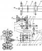
For the study of gas dynamics and heat transfer process in the piston engine of internal combustion, an experimental installation was designed and manufactured. It was developed on the basis of the engine model 11113 VAZ - Oka. When creating the installation, the prototype details were used, namely: connecting rod, piston finger, piston (with refinement), gas distribution mechanism (with refinement), crankshaft pulley. Figure 2.1 shows a longitudinal section of the experimental installation, and in Figure 2.2 is its transverse section.
Fig. 2.1. Lady cut of the experimental installation:
1 - elastic coupling; 2 - rubber fingers; 3 - rod cervical; 4 - native cervix; 5 - cheek; 6 - nut M16; 7 - counterweight; 8 - Nut M18; 9 - indigenous bearings; 10 - supports; 11 - Bearings connecting rod; 12 - rod; 13 - piston finger; 14 - piston; 15 - cylinder sleeve; 16 - cylinder; 17 - base of the cylinder; 18 - cylinder supports; 19 - Fluoroplast Ring; 20 - reference plate; 21 - hexagon; 22 - gasket; 23 - inlet valve; 24 - graduation valve; 25 - distribution shaft; 26 - camshaft pulley; 27 - crankshaft pulley; 28 - toothed belt; 29 - Roller; 30 - tensioner stand; 31 - tensioner bolt; 32 - Maslenka; 35 - Asynchronous Engine
Fig. 2.2. Transverse section of experimental installation:
3 - rod cervical; 4 - native cervix; 5 - cheek; 7 - counterweight; 10 - supports; 11 - Bearings connecting rod; 12 - rod; 13 - piston finger; 14 - piston; 15 - cylinder sleeve; 16 - cylinder; 17 - base of the cylinder; 18 - cylinder supports; 19 - Fluoroplast Ring; 20 - reference plate; 21 - hexagon; 22 - gasket; 23 - inlet valve; 25 - distribution shaft; 26 - camshaft pulley; 28 - toothed belt; 29 - Roller; 30 - tensioner stand; 31 - tensioner bolt; 32 - Maslenka; 33 - Insert profiled; 34 - measuring channel; 35 - Asynchronous Engine
As can be seen from these images, the installation is a natural model of the single-cylinder internal combustion engine of dimension 7.1 / 8.2. A torque from an asynchronous engine is transmitted through an elastic coupling 1 with six rubber fingers 2 on the crankshaft of the original design. The clutch used is capable of significantly compensate for the inconseability of the compound of the shafts of the asynchronous motor and the crankshaft of the installation, as well as to reduce dynamic loads, especially when starting and stopping the device. The crankshaft in turn consists of a connecting rod cervix 3 and two indigenous necks 4, which are connected to each other with cheeks 5. The rod cervix is \u200b\u200bpressed with tension in the cheek and fixed using nuts 6. To reduce vibrations to cheeks are fastened with anti-test bolts 7 . The axial movement of the crankshaft hinders the nut 8. The crankshaft rotates in the closed rolling bearings 9 fixed in the supports 10. Two closed rolling bearing 11 are installed onto a connecting rod neck, on which the connecting rod 12 is mounted. The use of two bearings in this case is associated with the landing size of the connecting rod . To the connecting rod with a piston finger 13, the piston 14 is mounted on the cast-iron sleeve 15, pressed in the steel cylinder 16. The cylinder is mounted on the base 17, which is placed on the cylinder supports 18. One wide fluoroplastic ring 19 is installed on the piston, instead of three standard Steel. The use of pig-iron sleeve and fluoroplastic ring provides a sharp decline in friction in pairs of piston - sleeves and piston rings - sleeve. Therefore, the experimental installation is capable of working a short time (up to 7 minutes) without a lubrication system and cooling system on the operating frequencies of the crankshaft rotation.
All major fixed elements of the experimental installation are fixed on the base plate 20, which, with two hexagons, 21 is attached to the laboratory table. To reduce the vibration between the hexagon and the support plate there is a rubber gasket 22.
The mechanism of timing experimental installation is borrowed from the VAZ 11113 car: a block head is used assembly with some modifications. The system consists of an inlet valve 23 and an exhaust valve 24, which are controlled using a camshaft 25 with pulley 26. The camshaft pulley is connected to the crankshaft pulley 27 with a toothed belt 28. On the crankshaft of the installation shaft placed two pulleys to simplify the drive belt tension system camshaft. The belt tension is controlled by roller 29, which is installed on the rack 30, and the tensioner bolt 31. Masliners 32 were installed for lubrication of the camshaft bearings, oil, of which gravity comes to the sliding bearings of the camshaft.
Similar documents
Features of the intake of the valid cycle. The influence of various factors on the filling of engines. Pressure and temperature at the end of the intake. The residual gas coefficient and the factors determining its magnitude. Inlet when accelerating the movement of the piston.
lecture, added 30.05.2014
The dimensions of the flow sections in the necks, cams for inlet valves. Profiling an unstressed cam leading one inlet valve. Pusher speed at the corner of the fist. Calculation of the springs of the valve and the camshaft.
course work, added 03/28/2014
General information about the internal combustion engine, its device and features of work, advantages and disadvantages. Engine workflow, fuel ignition methods. Search for directions to improve the design of an internal combustion engine.
abstract, added 06/21/2012
Calculation of the processes of filling, compression, combustion and expansion, determination of indicator, efficient and geometric parameters of the aviation piston engine. Dynamic calculation of the crank-connecting mechanism and calculation on the strength of the crankshaft.
course work, added 01/17/2011
Studying the features of the filling, compression, combustion and expansion process, which directly affect the workflow of the internal combustion engine. Analysis of indicator and effective indicators. Building indicator charts of the workflow.
coursework, added 30.10.2013
The method of calculating the coefficient and degree of unevenness of the supply of the piston pump with specified parameters, drawing up the corresponding graph. Piston pump suction conditions. Hydraulic installation calculation, its main parameters and functions.
examination, added 03/07/2015
Development of a draft 4-cylinder V-shaped piston compressor. The thermal calculation of the compressor installation of the refrigeration machine and the determination of its gas tract. Construction of an indicator and power diagram of the unit. The strength calculation of the details of the piston.
course work, added 01/25/2013
General characteristics of the circuit of an axial-piston pump with an inclined block of cylinders and a disc. Analysis of the main stages of calculating and designing an axial-piston pump with an inclined block. Consideration of the design of the universal speed regulator.
coursework, added 01/10/2014
Designing device for drilling-milling operations. The method of obtaining the workpiece. Construction, principle and conditions of operation of an axial-piston pump. Calculation of the error of the measuring instrument. Technological scheme for assembling the power mechanism.
thesis, added 05/26/2014
Consideration of thermodynamic cycles of internal combustion engines with heat supply under constant volume and pressure. Thermal engine calculation D-240. Calculation of intake processes, compression, combustion, expansion. Effective performance of DVS work.