Electrical power system. Injector system
Fuel injection
The era of the carburetor is replaced by the era of the injection engine, the power system is based on the fuel injection. Its main elements are: an electric fuel pump (located, as a rule, in the fuel tank), nozzles (or nozzle), the control unit of the DVS (the so-called "brains").
The principle of operation of this nutrition system is reduced to spraying fuel through the pressure under pressure generated by the fuel pump. The quality of the mixture varies depending on the engine operation mode and is controlled by the control unit.
An important component of such a system is a nozzle. Typology injector engines Based on the number of injectors used and location of their location. 
So, experts tend to allocate the following injector options:
- with distributed injection;
- with the central injection.
The distributed injection system involves the use of nozzles by the number of engine cylinders, where each cylinder serves its own nozzle involved in the preparation of a combustible mixture. The central injection system has only one nozzle to all cylinders located in the collector.
Features of diesel engine
No matter how the principle of action is based on the power system is based on diesel engine. Here, the fuel is injected directly into the cylinders in the sprayed form, where the process of mixing (mixing with air) is occurring, followed by ignition from the compression of a combustible mixture with a piston.
Depending on the fuel injection method, Diesel force aggregate Submitted by three main options:
- with direct injection;
- with a whirlpool injection;
- with a pre-commercial injection.
The dramatic and pre-commercial variants involve fuel injection into a special preliminary cylinder chamber, where it is partially flammable, and then moves to the main chamber or the cylinder itself. Here fuel, mixing with air, finally burns. The immediate injection involves the delivery of fuel immediately into the combustion chamber, followed by mixing it with air, etc. 
Another feature, which is distinguished by the diesel engine power system, is the principle of combustion of a combustible mixture. This is not due to the spark plug (like a gasoline engine), but on the pressure generated by the cylinder piston, that is, by self-ignition. In other words, in this case there is no need to apply spark plugs.
but cold Engine It will not be able to ensure the proper level of temperature required to ignite the mixture. And the use of incandescent candles will allow the necessary heating of combustion chambers.
Food system operation modes
Depending on the purpose and road Conditions The driver can apply different modes of motion. They are consistent with certain modes of operation of the power system, each of which is inherent in the fuel and air mixture of special quality.
- The composition of the mixture will be rich in the start of the cold engine. At the same time, air consumption is minimal. In this mode, the possibility of movement is categorically eliminated. Otherwise, this will lead to increased consumption of fuel and wear of the force aggregate details.
- The composition of the mixture will be enriched when using the mode " idle move", Which is used when moving" rolling "or the operation of the engine of the engine in a heated state.
- The composition of the mixture will be depleted when moving with partial loads (for example, on a flat road with an average speed at increased transmission).
- The composition of the mixture will be enriched in full load mode when the car is moving at high speed.
- The composition of the mixture will be enriched, approximate to the rich, when driving under sharp acceleration (for example, when overtaking).
The choice of the operating conditions of the power system, thus, should be justified by the need to move in a certain mode.
Malfunctions and service
During the operation of the vehicle, the fuel system of the car is experiencing loads leading to its unstable functioning or failure. The most common are the following malfunctions.
Insufficient receipt (or lack of admission) fuel in engine cylinders
Elected-quality fuel, long service life, environmental impact leads to contamination and clogging of fuel pipelines, tank, filters (air and fuel) and technological holes of the combustible mixture device, as well as a breakdown of the fuel pump. The system will require a repair that will be in a timely replacement of filtering elements, periodic (once every two or three years), clean the fuel tank, carburetor or injector nozzles and replacing the pump.
Loss of power of the economy
The fuel system malfunction in this case is determined by the violation of the quality adjustment and the amount of combustible mixture entering the cylinders. The elimination of malfunction is associated with the need to diagnose the combustible mixture preparation device.
Fuel leak
Fuel leakage - the phenomenon is very dangerous and categorically not allowed. This malfunction is included in the "List of faults ...", with which the movement of the car is prohibited. Causes of problems are losing in the loss of tightness with nodes and fuel system units. The elimination of malfunction is either in replacing the damaged elements of the system, or in tightening fasteners of fuel pipelines.
Thus, the power system is an important element DVS modern car And responsible for timely and uninterrupted fuel supply to the power unit.
The main elements that are nozzles.
The carburetor motor system includes: Fuel tank, filter-settling, fueling, fuel pump, fuel purification filter, air cleaner, intake pipe wire, exhaust pipe, receiving pipes, silencer, fuel level control devices.
Working system
When working the engine The fuel pump sucks fuel from the fuel tank and serves through the filters float Camera Carburetor. When the inlet tact in the engine cylinder is created a vacuum and air, passing through the air cleaner, enters the carburetor, where it is mixed with fuel pairs and in the form of a combustible mixture is supplied to the cylinder, and there, mixed with exhaust gas remains, a working mixture is formed. After completing the working stroke, the exhaust gases are pushed out by the piston in the exhaust pipeline and at the receiving pipes through the silencer in the surrounding medium.
|
Device TNVD YAMZ |
Power supply systems and exhaust gases of a car engine:
1 - air flow channel to the air filter; 2 - air filter; 3 - carburetor; 4 - Handle manual control air damper; 5 - manual control handle throttle; 6 - throttle control pedal; 7 - Fuel Wires; 8 - filter-sump; 9 - silencer; 10 - receiving pipes; 11 - exhaust pipeline; 12 - Filter of fine fuel purification; 13 - fuel pump; 14 - fuel level index; 15 - fuel level indicator sensor; sixteen - fuel tank; 17- Cover of the neck of the fuel tank; 18 - Crane; 19 - graduation tube of the muffler.
Fuel. As fuel in carburetor engines, gasoline is usually used, which is obtained as a result of oil refining.
Automotive gasoline, depending on the number of easily evaporating fractions, are divided into summer and winter.
For automotive carburetor engines, gasoline A-76, AI-92, AI-98, etc., and others are produced. The letter "A" indicates that the automotive gasoline, the figure is the smallest octane number characterizing the detonation resistance of gasoline. Isoattan has the largest detonation resistance, (its post-bone is taken for 100), the smallest - n-heptane (its resistance is 0). A octane number characterizing the detonation resistance of benzi-on, - the percentage of isochastane in such a mixture with a n-heptane, which is equivalent to the fuel to the tested fuel. For example, the fuel under study detonates the same way as a mixture of 76% iso-octane and 24% H-heptane. The octane number of this fuel is 76. The octane number is determined by two methods: Motor and Research-Telsky. When determining the octane number, the letter "and" is added to the second method in the gasoline brand. The octane number determines the pre-letm of compression.
Fuel tank. On the car install one or more fuel tanks. The volume of the fuel tank must provide 400-600 km of the car's mileage without refueling. The fuel tank consists of two welded halves made by a stamping from a wicked steel. Inside the tank there are partitions that give the stiffness of the design and prevent the formation of waves in the fuel. At the top of the tank, a bulk neck is welded, which is closed by a plug. Sometimes for the convenience of refueling the fuel fuel, a retractable neck with a mesh filter is used. On the upper wall of the tank, the fuel level indicator sensor and the fuel is the intake tube with a mesh filter. In the bottom of the tank there is a threaded hole for draining the sludge and removal of mechanical impurities, which is closed by a plug. The filling neck of the tank is closed with a tight plug, in the housing of which there are two valves - steam and air. A steam valve with a pressure increase in the tank opens and displays steam in environment. The air valve opens when fuel consumption and vacuum is created.
Fuel filters. To clean the fuel from mechanical impurities, filters are used coarse and fine cleaning. Filter-sump rough cleaning separates fuel from water and large mechanical impurities. The filter-sump consists of a housing, a sump and filtering element, which is collected from plates with a thickness of 0.14 mm. On the plates there are holes and protrusions with a height of 0.05 mm. The plate package is mounted on the rod and spring is pressed to the housing. In the assembled state between the plates there are cracks through which fuel passes. Large mechanical impurities and water are collected at the bottom of the sump and through the plug hole in the bottom periodically removed.

Fuel tank (s) and production of graduation (b) and intake (c) valves: 1- filter-sump; 2 - Bracket attachment bracket; 3 - tank fastening clamp; 4 - fuel level sensor in the tank; 5 - fuel tank; 6 - crane; 7 - tank tube; 8 - neck; 9 - Cork cladding; 10 - rubber gasket; P - cork housing; 12 - exhaust valve; 13 - Spring of the exhaust valve; 14 - inlet valve; 15 - tank tube lever; 16-Spring inlet valve.

Filter-sump: 1 - fuel wire to the fuel pump; 2 - enclosure laying; 3 - body cover; 4 - fuel wire from the fuel tank; 5 - laying of the filter element; 6 - filter element; 7-rack; 8 - sump; nine- drain plug; 10 - the rod of the filter element; 11 - Spring; 12 - plate of the filter element; 13 - hole in the plate for the passage of purified fuel; 14 - protrusions on the plate; 15 - hole in the plate for racks; 16 - plug; 17 - bolt fastening of body cover.

Filters of fine fuel filtering with filter elements: a - mesh; b - ceramic; 1- Corps; 2-inlet; 3- gasket; 4- filter element; 5-removable glass-sump; 6 - spring; 7-screw fastening of a glass; 8- Channel for fuel removal.
Filter of fine cleaning.
To clean the fuel from small mechanical impurities, filters of fine cleaning are used, which consist of a housing, a glass-sump and a filter mesh or ceramic element. Ceramic filter element is a porous material that provides the labyrinth movement of fuel. The filter is held by a bracket and a screw.
Fuel Wires join the fuel system devices and are made of copper, brass and steel tubes.
Fuel pump power supply pump
The fuel pump serves to supply fuel through the tank filters to the carburetor float chamber. Apply a diaphragm type pumps with an eccentric drive distribution Vala.. The pump consists of a housing in which the drive is attached is a biscuit lever with a spring, heads where inlet and discharge valves with springs and covers are placed. The edges of the diaphragm are clamped between the housing and head. The rod of the diaphragm to the drive lever is attached to be hinged, which allows the diaphragm to work with variable strokes.
When the biscuit lever (rocker) lowers the diaphragm down, the cavity above the diaphragm creates a vacuum, due to which the inlet valve opens and the nadiaphraggment cavity is filled with fuel. When running around the lever (pusher), the aperture rises up under the action of a return spring. Over the diaphragm, the pressure of the fuel is increased, the intake valve is closed, the injection valve opens and the fuel is opened through the fountal filter into the float chamber of the carburetor. When changing the filters, the float chamber is filled with fuel using the device for manual swap. In the case of the output of the diaphragm (crack, breakthrough, etc.), the fuel enters the lower part of the housing and flows through the control hole.
Air filter It serves to clean the air entering the carburetor, from dust. Dust contains the smallest quartz crystals, which, settled on the smeared surfaces of parts, causes their wear.
|
|

Requirements for filters:
. air purification efficiency from dust;
. Small hydraulic resistance;
. Sufficient digestibility:
. reliability;
. convenience in maintenance;
. Technological design.
By way of cleaning air, filters are divided into inertia and dry.
Inertia and oil filter It consists of a housing with an oil bath, covers, air intake and a filter element from synthetic material.
When the engine is operating, air passing through the ring gap inside the housing and, in contact with the surface of the oil, changes the direction of movement sharply. As a result, large dust particles in the air stick to the surface of the oil. Then the air passes through the filter element, is cleared of small dust particles and enters the carburetor. Thus, the air passes two-stage cleaning. When clogged, the filter is washed.
Dry air filter It consists of a housing, covers, air intake and a filtering element from porous cardboard. If necessary, the filter element is changed.
The system is powered by KAMAZ open space On the engine itself, on the bottom and frame of the car.
Purpose system assignment
The diesel engine power system serves to supply air and fuel to the engine cylinders in a given proportion and under a given pressure and removal of exhaust gases from them.
Total power supply device
Air power system.
Fuel system.
Fuel combustion products system

Fig. 3.
gas distribution mechanism of the car
Device of parts and nutrition systems

Fuel system
General device.
Serves for storing fuel reserve, for cleaning the fuel, to create it high pressureFor injection of fuel under pressure in engine cylinders.
Device:
- - Fuel tank is used to store fuel.
- - A powder filter of coarse cleaning is used to clean the fuel from coarse mechanical impurities.
- - Low pressure pump serves to supply fuel from tank to high pressure fuel pump.
- - Fuel filters of fine cleaning, for cleaning from small mechanical impurities.
- - The high pressure pump is used to create a high pressure and supply of fuel under pressure to the engine cylinders in accordance with the order of the cylinders.
- -Well wires:
Low pressure fuel. All fuel wires running tanks up to TNVD.
Fuel high pressure wires running from TNLD to nozzles.
Drainage fuel Wires, serve to drain extra fuel from the nozzles and the filter of fine cleaning back to the tank.
Fuel system devices device.
Fuel tank.
Used to store fuel reserve.

Device:
- -Corps consists of two stamped plates.
- -In the top of the filler neck and two holes covered with covers.
- - Thentree tank partitions, they limit the movement of fuel in the tank
- - The receiver is connected to the fuel with the wire, partially cleans the fuel.
- - The fuel level of the float type, is connected to the fuel level pointer wire.
Filter coarse fuel cleaning.
Designed for cleaning fuel from coarse mechanical pollution and water.

Device:
- - Clean closes the filter from above, there are two holes for supplying and removing fuel and four holes for fastening a glass on the lid. There are also brackets for fastening the filter on the carrier part of the car.
- -Stakan in it is the reassureer filter element. At the bottom of the glass accumulates sucks, to drain the sludge hole in the lower part of the glass, 4 threaded holes are arranged on the flange to connect it with the lid.
- - Totuzer for supplying and removing fuel.
- -Control filter, through it the fuel is filtered, at the outlet of the coarse filter.
- -Coable fuel on it flows into a glass, a drain plug with a sealing gasket closes a hole for draining the sludge.
- Suspendent laying of the lid.
- -Contentory bolts of washers.
Filters fine fuel purification.
Designed for fine fuel purification, from mechanical impurities.

Device:
- - A snap in it is one of the liner and three distinguished fuel channels to the pump, one channel for draining fuel into the fuel tank. It enters it through the reducing valve.
- - Conduction valve is located in the lid, which has fuel from the exhaust channel, to the tank by drainage fuel.
- - The cap with sealing gaskets is connected to the cover with the connecting axes, there are two filter elements in them.
- - Spring-based axis serve to attach the caps on the filter elements. Through them merges sucks.
- - The plug closes the hole in the cap, for draining fuel and sludge.
- - Filtering elements. Inside the steel perforated clip, behind it the filter corrugated cardboard.
Low pressure fuel pump.
TNND creates a low fuel pressure, in the fuel line from the tank to the pump, allows fuel to move aside the pump and pass through the filters.

- - Poverty (1)
- - holder (2)
- -Roller
- -Furn (3)
- - Love and exhaust valves (4,6)
Nozzle.
It serves for fuel injection into high-pressure engine, which creates an TNVD.
Device:
- -Corps There are springs, adjusting washers, rods, in the top of the housing are two threaded holes, they screw the fitting, one liner fuel, another drainage. With the outside of the housing is condensed with a ring.
- -Rost, located between the housing and the sprayer, it contains guide holes for the rod and needle. Through it passes the supply canal for fuel.
- -Spray. Inside sprayed channel that ends with an annular channel. In the sprayer there is a hole in which the needle and spray case is located.
- -Needle. The reviewing item is grouped along the sprayer, closes and opens the hole in the spray cone, supports the tightness of the sprayer.
- -Barbell. On one side, it relieves the needle on the other side, on the other side, the spring that presses the needle to the sprayer, the spring presses the needle to the sprayer through the bar.
- -Gulent gaskets, to adjust the efforts of pressed the needle to the sprayer.
- -Nut. Connects the package of supply and sprayer among themselves.

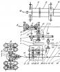
1 - body; 2, 32 - rollers of pushers; 3, 31 - axis of the rollers; 4 roller cut; 5 - heel pusher; 6 - tear; 7 - plate springs pusher; 8 - Pusher Spring: 9,34,43,45, 51 - washers; 10 - Swivel sleeve; 11 - plunger; 12, 13, 46, 55 - sealing rings; 14 - pin installation; 15 - Rake; 16 - Plunger's sleeve; 17 - section of the section; 18 - gasket of the injection valve; 19 is dischargeless; 20 - fitting; 21 - Section body flange; 22 - manual fuel pumping pump; 23 - Spring Cork; 24, 48 - gaskets; 25-cords of low pressure pump; 26 - Pump fuel pumping low pressure; 27 - Stem sleeve; 28 - Pusher Spring; 29 - pusher; 30 - Screw lock; 33, 52 - nuts; 35 - eccentric of low pressure pump drive; 36, 50 - swords; 37 - flange of the leading gear regulator; 38 - Truck leading gear regulator; 39 - gear leading regulator; 40 - stubborn sleeve; 41, 49 - bearing covers; 42 - Bearing; 44 - cam shaft; 47 - Cuffs with a spring assembly; 53 - fuel injection advance coupling; 54 - Reiki traffic jam; 56 - valve bypass; 57 - Reiki bushing; 58 - axis of lever rail; 59 - Adjustment pads.
General nutrition system
Supply system car engines Provides the flow of purified air and fuel to the cylinders. By the method of mixing formation, carburetor and diesel engines have significant differences. In diesel engines, the preparation of a combustible mixture occurs inside the cylinders, in carburetor engines - outside of cylinders (external mixture formation).
Combustible mixturethe mixture of sprayed and partially evaporated fuel with air is called in the cylinders during the engine operation. After the combustible mixture is mixed with the exhaust gases, which remained from the previous working cycle, it is called working mixture.
In the combustion process, carbon and hydrogen fuel are connected to air oxygen. Combustion can be complete or incomplete, depending on the amount of air entering the engine cylinders. With full combustion, combustion products consisting of excess oxygen, nitrogen, carbon dioxide and water vapor are formed.
In the event of a lack of oxygen, only part of the carbon of fuel combines and forms carbon dioxide, the rest of the carbon forms carbon monoxide.
For complete combustion of one kilogram of gasoline, 14, 7 kg of air, or 12 m3, is required. The mixture containing such a number of air is considered normaland the amount of air is theoretically necessary.
The different ratio of gasoline and air affects the fuel efficiency and engine power.
The engine running on a normal mixture develops the power close to the maximum and consumes fuel within the limits specified in the car manual.
The engine operating on the enriched mixture develops the maximum power and consumes a little more fuel than working on a normal mixture.
The engine running on a rich mixture develops less power, however, the fuel consumption increases significantly and during operation from exhaust pipe It goes black smoke pointing to incomplete fuel combustion.
Highly a rich mixwhere 1 kg of gasoline requires 5 or less kg of air does not flammify, it cannot work on it.
The depleted mixture is the most optimal for the engine operation, provides the greatest engineity of the engine compared to the mixtures of other compositions, but its power is somewhat lower than at a normal mixture.
The engine running on the poor mixture increases the fuel consumption and the engine power decreases, since the speed of its burning is very small. Working on such a mixture, the engine overheats, interruptions in the operation of cylinders, outbreaks in the carburetor appear.
During the start and warm-up warm engine warming, the mixture should be rich, for stable operation of the engine operating on small idling, is required, a rich mixture is required.
The mixture should be depleted when the engine works with incomplete load, which ensures the efficiency of the engine operation, and at full load, the mixture must be enriched so that the engine develops the maximum power.
With normal combustion of fuel, the speed with which the flame is propagated from the spark plug throughout the volume of the combustion chamber is approximately 30 to 40 m / s. Pressure rises quickly, but smoothly.
When the combustion of the mixture is carried out at a speed of over 200 m / s, the phenomenon is called detonation. Detonation is the nature of the explosion. The characteristic feature of detonation is ringing metal knots in the cylinders.
During detonation, the fuel burns not completely, the engine efficiency deteriorates, the power decreases, the bearings crumble crankshaft, Pistons and other engine parts are damaged due to high and sharp increase in pressure.
The mixture formation principle in diesel engines occurs in a very short time. It is necessary to spray the fuel on the smallest particles during this time and that each particle has around itself as much air, for complete combustion of fuel.
For this, fuel in the cylinder is injected under high pressure in the nozzle. Air pressure with compression tact in the combustion chamber is many times less. So that the power and engineering indicators and the engine economy were high and fuel completely burned, it is necessary that the fuel is injected into the cylinder until the piston arrives in the upper dead point.
This text is a familiarization fragment. From the book of the authorThe total information of the 7.62-mm PSS pistol is a personal weapon of a hidden attack and protection, designed for silent and flameless shooting at a distance of up to 50 m. The PSS is simple on the device and handling it, and constructively combines the original design solutions with
From the book of the author3.1. GENERAL INFORMATION Electrical energy by car is used to ignite the working mixture in the cylinders gasoline engines, to start the engine with an electrical starter, lighting, sound and light alarm, as well as for powering various additional
From the book of the author5.1. General information of the steering and suspension system interacts with each other. If problems occur in a single suspension element, it immediately significantly affects the steering characteristics of the car. For the maneuver of the front wheels
From the book of the author5.1. Table general information is the most difficult element of the publication. They allow them to systematize various data, making them comparable-mi, convenient for analysis, make it possible to establish an inspection between individual parameters. Thanks to its conciseness
From the book of the author2.1. General information All major methods of metal processing are known with deep antiquity. Passed a long way, has accumulated a huge luggage of practical knowledge and skills. The whole streets of urban artisans went to the past, from where the metal and a knock came from early morning
From the book of the author3.1. General information Difovka differs from forging by what is performed without heating and usually from sheet blanks. Therefore, it is also referred to as cold forged, or in painting. In the old Master with the use of paint (dipping) made from sheet gold and silver Cups,
From the book of the author5.1. General information Relief metalplastic and bass is much easier than manual chasing, do not require a large number of special devices. True, Basma is not so expressive compared to metal plastic, but it can be corrected, bringing bass to a complete species
From the book of the author9.1. General Information The term "Inlay" itself has a Latin origin: Incrustation - cover. Inlaid is the technique of decorating products by inciting into the surface (or singing) of various materials: metal, bones, precious wood, etc. Very often
From the book of the author6.2.1. General Production Production electrical Energy It is carried out mainly by electromashic generators, and consume its mainly electric motors. Therefore, rotating electrical machines are essential in electrical engineering. Many outstanding
From the book of the author6.4.1. General information to electrical apparatus (EA) includes a wide class of electrical devices used in the production, distribution and consumption of electrical energy. The area of \u200b\u200bdevices belonging to EA and their classification are constantly changing into
From the book of the author10.1. General information Materials in the development of civilization have always played a very important role. The famous American scientist A. Hippel expressed the opinion that the history of civilization can be described as a change of materials used by humanity. Their meaning emphasized Czechoslovak
From the book of the authorGENERAL INFORMATION The gearbox is a mechanism in which gears (gears) can be clutching in various combinations, obtaining various gear ratios - steps and serves to change the torque transmitted from the crankshaft
From the book of the authorGENERAL INFORMATION Front presenter bridge applied in cars increased passibility. It consists of a crankcase, the main transmission, differential and semi-axes. If the front leading bridge has control wheels, then the torque from the differential to the wheel hubs should
From the book of the authorGeneral to management systems vehicles include the steering system and brake systems, for the control of work serve control deviceslocated in the cab in front of the driver. The management authorities include: clutch pedal, pedal
From the book of the authorMalfunctions in the carburetor engine power system of about 50% of the engine malfunctions are caused by malfunctions in the operation of the engine power system. Faulty fuel system significantly affects the power and engineering engine. In most cases
From the book of the authorDiesel engine malfunctions In the event of malfunctions in the power system, the engine is hampered, the engine power decreases and the fuel consumption increases, there are interruptions in the operation of the cylinders, the stuffs, the release smoke occurs. Maintenance
The main thing for the purpose of the fuel system of the car are the supply of fuel from the tank, filtering, the formation of a combustible mixture and feeding it into the cylinders. There are several types of fuel systems for. The most common in the 20th century was carburetor system Feed a mixture of fuel. The next stage was the development of fuel injection using one nozzle, the so-called monofry. The use of this system made it possible to reduce fuel consumption. Currently, the third fuel supply system is used - injector. In this system, fuel under pressure is supplied directly to intake manifold. The number of nozzles is equal to the number of cylinders.

injector I.carburetor option
Fuel system device
All engine power systems are similarDifferent only by mixing methods. The composition of the fuel system includes the following elements:
- The fuel tank is designed to store fuel and is a compact container with a fuel intake device (pump) and, in some cases, elements of coarse filtering.
- The fuel lines are a complex of fuel tubes, hoses and are intended for transporting fuel to the mixing device.
- Mixing device ( carburetor, Monovpromsk, Injector) - This is a mechanism in which the fuel and air connection (emulsion) occurs for further submission to the cylinders in (intake tact).
- Block of the operation of the mixing device (injector power supply systems) - complex electronic device To manage work fuel injectors, Cutpan valves, control sensors.
- The fuel pump, usually submersible, is designed to pump fuel into the fuel line. It is an electric motor connected to a liquid pump in a hermetic case. Lubricated directly fuel and long operation with a minimum amount of fuel, leads to the failure of the engine. In some engines, the fuel pump was attached directly to the engine and operated by the rotation of the intermediate shaft, or camshed.
- Additional filters rough and fine cleaning. Installed filter elements in the fuel supply chain.
Principle of operation of the fuel system
Consider the work of the entire system as a whole. The fuel from the tank is absorbed by the pump and the fuel content through the cleaning filters is fed to the mixing device. In the carburetor, the fuel enters the float chamber, where then through calibrated jets is supplied to the mixing chamber. Mixing with air mixture through throttle valve Enters the intake manifold. After opening the inlet valve, it is fed to the cylinder. IN mono injection system Fuel is fed to the nozzle, which is controlled electronic block. At the right time, the nozzle opens, and the fuel enters the mixing formation chamber, where, as in carburetor system Mixed with air. Further the process is the same as in the carburetor.
IN injector system Fuel is fed to the nozzles that open control signals from the control unit. The nozzles are interconnected by the fuel supply, in which the fuel is always located. In all fuel systems there is a reverse fuel line, it merges over fuel in the tank.
The diesel engine power system is similar to gasoline. True, the fuel injection occurs directly into the combustion chamber of the cylinder, under greater pressure. Mixing formation occurs in the cylinder. For fuel supply under high pressure, a high pressure pump (TNVD) is used.