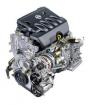
The power supply system of the carburetor engine. Injection system Purpose Device and operation of the engine power system
It is a whole range of devices. The main task becomes not just the supply of fuel to injection injectors, and also fuel supply under high pressure. Pressure is necessary for high-precision dosage injection into the cylinder combustion chamber. The diesel power system performs the following major functions:
- dosing a strictly defined amount of fuel based on the engine load in one or another mode of its operation;
- effective fuel injection at a predetermined period of time with a certain intensity;
- spraying and the most uniform distribution of fuel in terms of the combustion chamber in diesel engine cylinders;
- pre-filtering fuel before fuel supply in power supply pumps and injection nozzles;
Most of the requirements for the diesel engine power supply system put forward with the fact that diesel fuel It has a number of specific features. This kind of fuel is a mixture of kerosene and gas-free solar fractions. Diesel fuel is obtained after gasoline outflow is implemented from oil.
Diesel fuel has a number of properties, the main of which is considered to be the indicator of self-flammability, which is estimated by the cetane number. The types of diesel fuel presented on sale have a cetane number at a mark of 45-50. For modern diesel units, the best fuel is fuel with a large indicator of the cetane number.
The diesel engine power supply system provides the supply of well-purified diesel fuel to the cylinders, the pump compresses fuel to high pressure, and the nozzle supplies it in the combustion chamber sprayed on the smallest particles. The sprayed diesel fuel mixes with a hot (700-900 ° C) air, which is heated to such a temperature from high compression in the cylinders (3-5 MPa) and self-propagates.
Please note the working mixture in the diesel engine is not set in price by a separate device, and flammable independently from a heated air contact. This feature is greatly distinguished by diesel engine from gasoline analogues.
Diesel fuel has a higher density relatively with gasoline, and also has the best lubricity. No less an important characteristic There is viscosity, frosted temperature and purity of diesel fuel. The temperature of the frozen allows you to divide the fuel into three basic fuel varieties :.
Diesel Diesel Food System Device Scheme
Supply system diesel engine Consists of the following basic elements:
- fuel tank;
- filters of coarse cleaning of diesel fuel;
- filters of fine fuel purification;
- fuel pumping pump;
- high pressure fuel pump (TNVD);
- injector nozzles;
- low Pressure Pipeline;
- high pressure hut;
- air filter;
Additional elements partially becomes the electric pump, the release of exhaust gases, saw filters, silencers, etc. The diesel engine power supply system is commonly divided into two groups of fuel equipment:
- diesel equipment for the occasion of fuel (fuel-feed);
- diesel apparatus for air supply (air supploring);
The fuel supply equipment can have a different device, but today the system of separated type is most common. In such a system, the high pressure fuel pump (TNLD) and the nozzles are implemented as separate devices. Fuel is served in a diesel engine on high and low pressure highways.
Diesel fuel is stored, filtered and fed to an electric pressure under low pressure by means of a low pressure highway. The high-pressure high-pressure highway raises pressure in the system for carrying out the supply and injection of a strictly defined amount of fuel into the working chamber of the combustion of the diesel engine at a specified moment.
Two pumps are present in the diesel power system:
- fuel pumping pump;
- high pressure fuel pump;
The fuel pumping pump provides fuel supply from fuel tank, pumps fuel through a coarse and fine filter. The pressure that creates the fuel-pumping pump allows the supply of fuel to the low pressure fuel supply to the high pressure fuel pump.
TNVD sells fuel supply to high pressure nozzles. The feed occurs in accordance with the order of operation of the diesel engine cylinders. High pressure fuel pump has a certain number of identical sections. Each of these sections of the TNVD corresponds to a specific diesel engine cylinder.
There is also a system for the nutrition of diesel engines of unproduced type and is used on diesel two-stroke engines. In such a system, the high-pressure fuel pump and the nozzle are combined in one device called the pump-nozzle.
These motors work hard and noisy, have a short service life. In the design of their power system there are no high-pressure fuel lines. This type of engine does not have much spread.
Let's return to the mass design of the diesel engine. Diesel nozzles are located in the head of the cylinder block () diesel engine. Their main task becomes accurate spraying of fuel in the engine combustion chamber. The fuel-blowing pump delivers a large amount of fuel to the pump. The resulting excess of fuel and the air penetrating the fuel feed system is returned to the fuel tank using special pipelines, which are called drainage.
Injector diesel nozzles are two types:
- closed diesel nozzle;
- open diesel nozzle;
Four-stroke diesel motors Preferably receive closed-type nozzles. In such devices, nozzle nozzles, which are a hole, are closed with a special locking needle.
It turns out that the inner cavity, located inside the housing of the injectors, is communicated with the combustion chamber only during the opening of the nozzle and at the time of the injection of diesel fuel.
A key element in the injector design is a sprayer. The sprayer receives from one to the whole group of nozzle holes. It is these holes that form a fuel torch at the time of injection. The form of a torch depends on their quantity and location, as well as the throughput of the nozzle.
Turbodizel power supply system
Recent fuel system Diesel: Signs of malfunction and diagnostics. How to independently find the air suction site, ways to solve the problem. 
The main elements that are nozzles.
In the system carburetor Engine Enter: Fuel tank, filter-settling, fueling, fuel pump, fuel purification filter, air cleaner, intake pipe wire, exhaust pipe, receiving pipes, silencer, fuel level control devices.
Working system
When working the engine The fuel pump sucks fuel from the fuel tank and serves through the filters float Camera Carburetor. When the inlet tact in the engine cylinder is created a vacuum and air, passing through the air cleaner, enters the carburetor, where it is mixed with fuel pairs and in the form of a combustible mixture is supplied to the cylinder, and there, mixed with exhaust gas remains, a working mixture is formed. After completing the working stroke, the exhaust gases are pushed out by the piston in the exhaust pipeline and at the receiving pipes through the silencer in the surrounding medium.
|
Device TNVD YAMZ |
Power supply systems and exhaust gases of a car engine:
1 - air flow channel to the air filter; 2 - air filter; 3 - carburetor; 4 - handle of manual air damper control; 5 - manual control handle throttle; 6 - throttle control pedal; 7 - Fuel Wires; 8 - filter-sump; 9 - silencer; 10 - receiving pipes; 11 - exhaust pipeline; 12 - Filter of fine fuel purification; 13 - fuel pump; 14 - fuel level index; 15 - fuel level indicator sensor; 16 - fuel tank; 17- Cover of the neck of the fuel tank; 18 - Crane; 19 - graduation tube of the muffler.
Fuel. As fuel in carburetor engines, gasoline is usually used, which is obtained as a result of oil refining.
Automotive gasoline, depending on the number of easily evaporating fractions, are divided into summer and winter.
For automotive carburetor engines, gasoline A-76, AI-92, AI-98, etc., and others are produced. The letter "A" indicates that the automotive gasoline, the figure is the smallest octane number characterizing the detonation resistance of gasoline. Isoattan has the largest detonation resistance, (its post-bone is taken for 100), the smallest - n-heptane (its resistance is 0). A octane number characterizing the detonation resistance of benzi-on, - the percentage of isochastane in such a mixture with a n-heptane, which is equivalent to the fuel to the tested fuel. For example, the fuel under study detonates the same way as a mixture of 76% iso-octane and 24% H-heptane. The octane number of this fuel is 76. The octane number is determined by two methods: Motor and Research-Telsky. When determining the octane number, the letter "and" is added to the second method in the gasoline brand. The octane number determines the pre-letm of compression.
Fuel tank. On the car install one or more fuel tanks. The volume of the fuel tank must provide 400-600 km of the car's mileage without refueling. The fuel tank consists of two welded halves made by a stamping from a wicked steel. Inside the tank there are partitions that give the stiffness of the design and prevent the formation of waves in the fuel. At the top of the tank, a bulk neck is welded, which is closed by a plug. Sometimes for the convenience of refueling the fuel fuel, a retractable neck with a mesh filter is used. On the upper wall of the tank, the fuel level indicator sensor and the fuel is the intake tube with a mesh filter. In the bottom of the tank there is a threaded hole for draining the sludge and removal of mechanical impurities, which is closed by a plug. The filling neck of the tank is closed with a tight plug, in the housing of which there are two valves - steam and air. A steam valve, when improving pressure in the tank, opens and displays steam into the environment. The air valve opens when fuel consumption and vacuum is created.
Fuel filters. To clean the fuel from mechanical impurities, filters are used coarse and fine cleaning. Filter-sump rough cleaning separates fuel from water and large mechanical impurities. The filter-sump consists of a housing, a sump and filtering element, which is collected from plates with a thickness of 0.14 mm. On the plates there are holes and protrusions with a height of 0.05 mm. The plate package is mounted on the rod and spring is pressed to the housing. In the assembled state between the plates there are cracks through which fuel passes. Large mechanical impurities and water are collected at the bottom of the sump and through the plug hole in the bottom periodically removed.

Fuel tank (s) and production of graduation (b) and intake (c) valves: 1- filter-sump; 2 - Bracket attachment bracket; 3 - tank fastening clamp; 4 - fuel level sensor in the tank; 5 - fuel tank; 6 - crane; 7 - tank tube; 8 - neck; 9 - Cork cladding; 10 - rubber gasket; P - cork housing; 12 - exhaust valve; 13 - Spring of the exhaust valve; 14 - inlet valve; 15 - tank tube lever; 16-Spring inlet valve.

Filter-sump: 1 - fuel wire to the fuel pump; 2 - enclosure laying; 3 - body cover; 4 - fuel wire from the fuel tank; 5 - laying of the filter element; 6 - filter element; 7-rack; 8 - sump; 9- drain plug; 10 - the rod of the filter element; 11 - Spring; 12 - plate of the filter element; 13 - hole in the plate for the passage of purified fuel; 14 - protrusions on the plate; 15 - hole in the plate for racks; 16 - plug; 17 - bolt fastening of body cover.

Filters of fine fuel filtering with filter elements: a - mesh; b - ceramic; 1- Corps; 2-inlet; 3- gasket; 4- filter element; 5-removable glass-sump; 6 - spring; 7-screw fastening of a glass; 8- Channel for fuel removal.
Filter of fine cleaning.
To clean the fuel from small mechanical impurities, filters of fine cleaning are used, which consist of a housing, a glass-sump and a filter mesh or ceramic element. Ceramic filter element is a porous material that provides the labyrinth movement of fuel. The filter is held by a bracket and a screw.
Fuel Wires join the fuel system devices and are made of copper, brass and steel tubes.
Fuel pump power supply pump
The fuel pump serves to supply fuel through the tank filters to the carburetor float chamber. Apply a diaphragm type pumps with an eccentric drive distribution Vala.. The pump consists of a housing in which the drive is attached is a biscuit lever with a spring, heads where inlet and discharge valves with springs and covers are placed. The edges of the diaphragm are clamped between the housing and head. The rod of the diaphragm to the drive lever is attached to be hinged, which allows the diaphragm to work with variable strokes.
When the biscuit lever (rocker) lowers the diaphragm down, the cavity above the diaphragm creates a vacuum, due to which the inlet valve opens and the nadiaphraggment cavity is filled with fuel. When running around the lever (pusher), the aperture rises up under the action of a return spring. Over the diaphragm, the pressure of the fuel is increased, the intake valve is closed, the injection valve opens and the fuel is opened through the fountal filter into the float chamber of the carburetor. When changing the filters, the float chamber is filled with fuel using the device for manual swap. In the case of the output of the diaphragm (crack, breakthrough, etc.), the fuel enters the lower part of the housing and flows through the control hole.
Air filter It serves to clean the air entering the carburetor, from dust. Dust contains the smallest quartz crystals, which, settled on the smeared surfaces of parts, causes their wear.
|
|

Requirements for filters:
. air purification efficiency from dust;
. Small hydraulic resistance;
. Sufficient digestibility:
. reliability;
. convenience in maintenance;
. Technological design.
By way of cleaning air, filters are divided into inertia and dry.
Inertia and oil filter It consists of a housing with an oil bath, covers, air intake and a filter element from synthetic material.
When the engine is operating, air passing through the ring gap inside the housing and, in contact with the surface of the oil, changes the direction of movement sharply. As a result, large dust particles in the air stick to the surface of the oil. Then the air passes through the filter element, is cleared of small dust particles and enters the carburetor. Thus, the air passes two-stage cleaning. When clogged, the filter is washed.
Dry air filter It consists of a housing, covers, air intake and a filtering element from porous cardboard. If necessary, the filter element is changed.
The car power system is used to prepare the fuel mixture. It consists of two elements: fuel and air. The engine power system immediately performs several tasks: cleansing the elements of the mixture, obtaining the mixture and its feed to the engine elements. Depending on the car power system used, the composition of the combustible mixture differs.
Types of power systems
The following types of engine power systems differ, characterized by the mixture area:
- inside motor cylinders;
- outside motor cylinders.
The fuel system of the car in the formation of a mixture outside the cylinder is divided into:
- fuel system with carburetor
- using one nozzle (with mono injection)
- injector
Purpose and composition of the fuel mixture
For uninterrupted operation of the engine of the car requires a certain fuel mixture. It consists of air and fuel mixed by a certain proportion. Each of these mixtures is characterized by the amount of air occurring per unit of fuel (gasoline).
For the enriched mixture, the presence of 13-15 parts of air per part of the fuel is characterized. This mixture is supplied at medium loads.
The rich mixture contains less than 13 parts of air. Applied at large loads. There is an increased gasoline consumption.
The normal mixture is characterized by the presence of 15 parts of air onto a part of the fuel.
The depleted mixture contains 15-17 parts of air and is used at medium loads. Economic fuel consumption is ensured. The poor mixture contains more than 17 parts of air.
Total power supply device
In the engine power system, there are the following main parts:
- tank for fuel. Serves for storing fuel, contains a pump for downloading fuel and sometimes filter. It has compact dimensions
- fuel line. This device provides fuel flow into a special blending device. Consists of various hoses and tubes
- matching device. Designed to obtain a fuel mixture and feed to the engine. Such devices may be an injection system, monofrying, carburetor
- control unit (for injectors). Consists of an electronic unit, managing the operation of the mixing system and signaling about emerging failures in
- fuel pump. We are needed for fuel admission to the fuel line
- filters for cleaning. Required to obtain pure mixtures
Carburetor fuel supply system
This system is distinctive in that the mixing formation occurs in a special device - carburetor. It hits the mixture from it in the desired concentration into the engine. The engine power system device contains such elements: fuel tank, cleaning filters for fuel, pump, air filter, two pipelines: intake and exhaust, carburetor.
The diagram of the engine power system is implemented so. The tank is fuel, which will be used to feed. It enters the carburetor through the fuel line. The feed process can be implemented using a pump or a natural way using a samothek.
In order for the fuel feed to be carried out in the carburetor chamber, it is necessary to be located below the fuel tank. This scheme is not always possible to implement in the car. But the use of the pump makes it possible not to depend on the tank position relative to the carburetor.
The fuel filter cleans the fuel. Thanks to him, mechanical particles and water are removed from the fuel. Air falls into the carburetor chamber through special filter For air, cleaning it from dust particles. In the chamber there is a mixing of two purified components of the mixture. Finding into the carburetor, fuel enters the float chamber. And after the mixing formation is sent to the chamber, where it is connected to the air. Through the throttle, the mixture comes into intake manifold. Hence it goes to cylinders.
After working out the mixture of gases from cylinders is removed using an exhaust manifold. Next, from the collector, they are sent to the muffler, which suppresses their noise. From it they enroll in the atmosphere.
In detail about the injection system
At the end of the last century, the carburetor power systems began to be intensively replaced with new injectors operating systems. And not just like that. Such an engine power system has a number of advantages: a smaller dependence on environmental properties, economical and reliable operation, exhaust less toxic. But they have a flaw - this is a high sensitivity to the quality of gasoline. If this is not observed, then malfunctions may occur in the work of some system elements.
"Injector" is translated from English like a nozzle. Single-point (monodular) engine power system diagram looks like this: fuel is fed to the nozzle. The electronic unit submits signals to it, and the nozzle opens at the right moment. Fuel is sent to the mixing chamber. Further, everything happens as in the carburetor system: a mixture is formed. Then it passes the inlet valve and enters the engine cylinders.
The engine of the engine power system, organized by the injectors, the following. This system is characterized by the presence of several nozzles. These devices receive signals from a special electronic unit and open. All these nozzles are connected to each other using the fuel line. It always has in stock fuel. Extra fuel is removed on the opposite fuel line back to the tank.
Electronasus supplies fuel to the ramp, where overpressure is formed. The control unit sends a signal to the nozzles, and, they open. The fuel is injected into the intake manifold. Air, passing the throttle knot, falls there. The resulting mixture enters the engine. The amount of the required mixture is adjusted by opening throttle valve. As soon as the tact of injection ends, the nozzles are closed again, the fuel supply stops.
Purpose, device and operation of the supply system fuel
The fuel engine power system is designed to place the fuel reserve by car, cleaning, spraying the fuel and the uniform distribution of it by cylinders in accordance with the order of the engine.
The KAMAZ-740 engine uses a separation type fuel system (i.e., high-pressure fuel pump functions and nozzles are separated). It includes (Fig. 37) Fuel tanks, fuel filter Rough cleaning, fuel filter of thin cleaning, low pressure pump * Low pressure pump, fuel pump pump, high pressure fuel pump (TNVD) with a fuel regulator and automatic fuel injection ahead, nozzles, high and low pressure fuel lines and control and measuring instruments.
Fuel from the fuel tank under the action of the vacuum generated by the fuel-pumping pump, through the filters of coarse and thin purification by low-pressure fueling powdles is supplied to the high pressure fuel pump. In accordance with the order of the engine (1-5-4-2-6-3-7-8-8), the TNVD supplies fuel under high pressure and certain portions through the nozzles in the combustion chamber of the engine cylinders. Injectors fuel sprayed. Excess the fuel, and with them and the air in the system through the ottld valve and the valve-fat valve of the fine cleaning filter are discharged into the fuel tank. Fuel surceded through the gap

Fig. 37. Fuel engine power system:
1 - fuel tank; 2 - fuel line to coarse filter; 3 - tee; 4 - Filter of coarse fuel purification; 5 - drain drainage fuel line injectors of the left row; 6 - nozzle; 7 - Sliding fuel line to low pressure pump; 8 - high pressure fuel pipe; 9 - manual fuel pumping pump; 10 is a top-level low pressure pump; 11 - fuel line to fine filter; 12 - high pressure fuel pump; 13 - fuel line to the electromagnetic valve; 14 - electromagnetic valve; / 5-drain drainage fuel line injectors of the right row; 16 - flare candle; P - drainage fuel pipeline of high pressure pump; 18 - Filter of fine fuel purification; 19 - Supporting fuel line to high pressure pump; 20 - drainage fuel filter fuel pipeline; 21 - drain fuel line; 22 - distribution crane

Fig. 38. Fuel tank:
1 - bottom; 2 - partition; 3 - body; 4 - plug crane; 5 - bulk tube; 6 - plug of bulk pipe; 7-second tape; 8 - Bracket Bracket Bracket
Fuel tanks (Fig. 38) are intended for accommodation and storage by car defined. Fuel supply. The KAMAZ-4310 car has two tanks with a capacity of 125 liters each. They are located on both sides of the car on the spars of the frame. The tank consists of two halves, stepped out of sheet steel and connected by welding; For corrosion protection, it is overwritten from the inside.
Inside the tank there are two partitions that serve to mitigate hydraulic fuels of fuel on the wall when the car is moving. The tank is equipped with a filling neck with a pull-out pipe, a filter grid and a hermetic lid. At the top of the tank, the fuel indicator sensor of the fuel level of the fuel is installed, a tube performing the role of an air valve. At the bottom of the tank, the intake tube and a fitting with a crane for draining sludge. At the end of the intake tube there is a strainer.
Filter of coarse fuel purification (Fig. 39) is intended for pre-purification of the fuel entering the fuel supply pumping pump. Mounted on the left side on the car frame. It consists of a housing, a reflector with a filter grid, a distributor, a sedator, a glass of filter, applying and discharge fittings with gaskets. A glass with a lid is connected by four bolts through a rubber sealing "JU gasket. A drain plug screws into the lower part of the glass.
The fuel coming through the tubing tank fitting is supplied to the distributor. Large extraneous particles and water are collected at the bottom of the glass. From the upper part of the fuel through the mesh filter, it is supplied to the discharge piece, and from it to the fuel supply pumping pump.
Filter of fine fuel purification (Fig. 40) is designed for final fuel purification before entering it into a high-pressure fuel pump. The filter is installed in the rear of the engine at the highest point of the power system. Such an installation provides air collection that has fallen into the system, and its removal in the fuel tank through the magnifier valve. The filter consists of a housing,
two filtering elements, two caps with welded rods, valve-gibera, supplying and discharge fittings with sealing gaskets, seal elements. The housing is cast from aluminum alloy. It contains channels for supplying and removing fuel, cavity to install valve-gibber and ring poles for installing the caps.
Replaceable cardboard filter elements are made of highly porous Cardboard type ETFS. The end seal of the elements is carried out by the upper and lower seals. The dense fit of the elements to the filter housing is provided by springs installed on the rods of the caps.
The magnifier valve is designed to remove air in the system. It is installed in the filter housing and consists of a cap, the springs of the valve, cork, adjusting washer, sealing washer. The fat valve opens when the pressure in the cavity in front of the valve is equal to 0.025 ... 0.045 MPa (0.25 ... 0.45 kgf / cm2), and at a pressure of 0.22 ± 0.02 MPa (2.2 ± 0.2 kgf / cm2) Begins torture fuel.
The fuel under pressure from the fuel-pumping pump fills the inner cavity of the cap and is pushed through the filter element, mechanical impurities remain on the surface. Purified fuel from the inner cavity of the filter element is supplied to the intake cavity of the pump.

Fig. 39. Filter of coarse fuel purification:
1 - drain plug; 2 - a glass; 3 - sedative; 4 - Mesh filtering; 5 - reflector; 6 - distributor; 7 - bolt; 8- flange; 9-ring sealing; 10 - housing
The low-pressure fuel pumping pump is designed to supply fuel through coarse and thin cleaning filters to the intake cavity of the TNVD. Piston type pump with drive from eccentric cam shaft TNVD. Pressure supply 0.05 ... 0.1 MPa (0.5 ... 1 kgf / cm2). The pump is installed on the back cover of the TNVD. The fuel pumping pump (Fig. 41, 42) consists of a housing, piston, piston springs, piston pusher, pusher rod, pusher springs, rod sleeve guide, inlet valve, injection valve.
Pig-iron pump housing. It contains channels and cavities for piston and valves. The cavities under the piston and above the piston are connected by the channel through the injection valve.
The pusher is designed to transmit effort from the eccentric cam shaft piston. Roller-type pusher.
The eccentric cam shaft of the pump through the pusher and the rod informs the piston of the pump (see Fig. 41) a reciprocating movement.

Fig. 40. Filter of fine fuel purification:
1 - body; 2 - bolt; 3 - sealing washer; 4 - traffic jam; 5, 6 - gaskets; 7 - element filtering; 8 - Cap; 9 - spring filter element; 10 - drain plug; 11 - Rod.
When lowering the pusher, the piston under the action of the spring moves down. In the suction cavity, it creates a vacuum, the inlet valve opens and passes the fuel into the above-piston cavity. At the same time, fuel from the pouring cavity through a fine cleaning filter enters the intake Channels of the TNVD. When the piston moves up the ink valve closes and fuel from the pickup cavity through the injection valve enters the cavity under the piston. When the pressure in the injection line B rises, the piston stops after the pusher move down, but remains in a position that is determined by the equilibrium of the forces from the fuel pressure on one side and the spring force on the other. Thus, the piston makes no complete move, but a partial one. Thus, the performance of the pump will be determined by fuel consumption.
Manual fuel pumping pump (see Fig. 42) Designed to fill the fuel system and remove air from it. The piston type pump is attached on the housing of the brawl pump through the sealing copper puck.
The pump consists of a housing, piston, cylinder, piston rod and handle, support plate, inlet valve (total with a fuel pumping pump).
Filling and pumping the system is carried out by the movement of the handle with the rod up-down. When the handle is moving up in the rowing space, a vacuum is created. The intake valve opens and fuel enters the cavity above the piston of the fuel pumping pump. When the handle moves down, the fuel-pumping pump discharge valve opens and fuel under pressure enters the injection line. Next, the process is repeated.
After pumping, the handle must be tightly screwed onto the top threaded cylinder shank. In this case, the piston is yarring to the rubber gasket, sealing the inlet cavity of the fuel-pumping pump.

Fig. 41. Scheme of the fuel-pumping pump of low pressure and manual fuel pumping pump:
1 - Eccentric Drive Drive; 2 - pusher; 3 - piston; l - intake valve; 5 - manual pump; 6 - Purpose 4 Valve
The high pressure fuel pump (TNVD) is designed to supply dosage portions of fuel under high pressure into the engine cylinders in accordance with the order of their operation.

Fig. 42. Fuel pumping pump:
1 - Eccentric Drive Drive; 2 - roller pusher; 3 - case (cylinder) pump; 4 - spring pusher; 5 - rod of the pusher; 6 - Stem sleeve; 7 - piston; 8 - Piston Spring; 9 - High Pressure Pump Corps; 10 - inlet valve seat; 11- Housing of low pressure fuel pumping pump; 12 - inlet valve; 13 - Valve Spring; / 4 - manual pumping pump; 15 - washer; 16 - the plug of the discharge valve; 17 - the spring of the discharge valve; 18 - low pressure fuel pump discharge valve

Fig. 43. High pressure fuel pump: 1 - rear regulator cover; 2, 3 - the leading and intermediate gear of the regulator of the frequency of rotation; 4- driven gear of the regulator with cargo holder; 5 - cargo axis; 6 - cargo; 7-coupling of goods; 8 - Finger lever; 9 - corrector; 10 - lever of the springs of the regulator; 11 - Rake; 12 - rail sleeve; 13 - reduction valve; 14 - Reiki traffic jam; 15 - YUFTA fuel injection; 16 - cam shaft; 17, - pump housing; 18 - Pump section
The pump is installed in the collapse of the cylinder block and operates from the camshaft gear through the pump drive gear. The direction of rotation of the cam shaft from the drive side is right.
The pump consists of a housing, a cam shaft (see Fig. 43), eight pumping sections, an all-mode regulator of the rotational frequency, fuel injection and fuel pump drive coupling.
The TNLD housing is designed to place pump sections, cam shaft and rotational speed control. Molding from aluminum alloy, it contains inlet and cut-off channels and cavities for installation and fastening of pumping sections, cam shaft with bearings, gear of the controller drive, supplying and reducing fuel fittings. In the rear end of the pump housing, the lid of the regulator is attached, in which the low-pressure fuel pumping pump is located with the pumping pump of the fuel. On top of the lid, the fitting with the oil oil tube for lubricating the parts of the pump under pressure is screwed. The oil from the pump merges along the tube connecting the lower hole of the regulator cover with the hole in the block collapse. The upper cavity of the TNVD body closes with a lid (see Fig. 44), on which the control levers of the speed controller and two protective covers are located fuel sections pump. The cover is installed on two pins and is fastened with bolts, and protective covers - with two screws. At the front end of the pump housing at the outlet from the shut-off channel, a fitting was screwed with a ball-type bypass valve supporting the excess fuel pressure in the pump 0.06 ... 0.08 MPa (0.6 ... 0.8 kgf / cm2). At the bottom of the pump housing, a cavity is made to install a cam shaft.
The cam tree is designed for the movement of pumping sections in plungers and ensuring a timely fuel supply to the engine cylinders. The cam shaft is made of steel. The working surfaces of the cams and the supporting necks are cemented to a depth of 0.7 ... 1.2 mm. Due to the co-circular design of the pump, the cam shaft has a smaller length and, therefore, has a higher rigidity. The shaft rotates in two tapered bearings, the internal roles of which are pressed on the shaft neck. The axial clearance of the cam shaft 0.1 mm is regulated by gaskets installed under the bearing cover. For sealing cam shaft in the lid there is a rubber cuff. At the front cone end of the cam shaft on the segment key, an automatic coupling of the fuel injection angle is installed. At the rear end of the cam shaft, a stubborn sleeve is mounted, the leading gear of the regulator assembly, and on the prismatic key - the flange of the leading gear of the regulator. The flange is made together with the eccentric of the fuel-powder pumping pump. The torque from the cam shaft on the leading gear of the regulator is transmitted through the flange through rubber crackers. When the cam shaft rotates, the force is transmitted to roller pushers and through the pushers' stains to plungers of pumping sections. Each pusher from rotation is fixed with a sukhara, the protrusion of which is included in the pump sliding groove. Due to changes in thickness, the fifth is regulated by the start of fuel supply. When installing the fifth of greater thickness, the fuel starts to be supplied earlier.

Fig. 44. Controller cover:
1 - Bolt of adjustment of the launcher; 2 - stop lever; 3 - Bol * regulation of the stop lever; 4 - bolt restrictions of the maximum rotational speed; 5 - control lever regulator (fuel pump rail); 6 - bolt restrictions of the minimum rotation frequency; I - work; IT - off
Pump section (Fig. 45, a) is a part of the high-pressure fuel pump, which is dosing and feeding the fuel to the nozzle. Each pump section consists of a corpurz, plunger pair, swivel sleeve, springs plunger, discharge valve, pusher.
The enclosure of the section has a flange, with which the section is attached on the heels, screwed into the pump housing. Holes in the flange under the studs have an oval shape. This allows you to rotate the pumping section to regulate the uniformity of the fuel supply by individual sections. When you turn the section counterclockwise, the cycle feed increases, clockwise decreases. In the section of the section, two holes are made for the passage of fuel from the channels in the pump to the holes in the plunger sleeve (A, B), the hole for installing the pin fixing the position of the sleeve and the plunger relative to the section of the section, and the slot for placing a swivel sleeve.
Plunger pair (Fig. 45, b) is the node of the pump section, directly intended for dosing and fuel supply. Plunger pair includes a plunger and plunger bushing. They represent a precision pair. Made from chromolibdden steel, are undergoed by quenching, followed by a deep cold processing to stabilize the properties of the material. Work surfaces of the bushings and plunger nitrate.

Fig. 45. Section of the high pressure fuel pump:
a - design; B - the upper part of the plunger pair; A - cavity of the fuel pump injection; B - cutoff cavity; 1 - pump housing; 2- pusher section; 3 - heel pusher; 4 - Spring: 5, 14-Plunger Section; 6, 13 - Plunger's sleeve; 7 - discharge valve; 8 - fitting; 9 - section of the section; 10 - shut-off edge of the screw groove of the plunger; 11 - Rake; 12 - Plunger Rotary Bushing
The plunger is a movable piece of plunger pair and performs the role of piston. The plunger in the upper part has axial drilling, two spiral grooves made from two sides of the plunger, and a radial drilling connecting the axial drilling and grooves. The spiral groove is designed to change the cycle supply of fuel due to the rotation of the plunger, and consequently, the grooves relative to the cut-off plunger sleeve. The rotation of the plunger relative to the sleeve is carried out by the fuel pump rail through the spikes of the plunger. There is a label on the outer surface of one spike. When assembling the section, the tag on the plunger spike and the slot in the case of the section to install the leash of the swivel sleeve must be on the one hand. The presence of the second groove provides the hydraulic unloading of the plunger from the side effort. Due to this, the reliability of the pump section is increasing.
The seal between the sleeve and the section of the section is provided by a ring of oil-resistant rubber installed in the annular groove of the sleeve.
The discharge valve and its saddle are made of steel, hardened and treated with deep cold. The valve and saddle are a precision pair, in which the replacement of one part on the same name from another set is not allowed.
The discharge valve is located at the upper end of the sleeve and pressed to the saddle of the spring. The saddle of the discharge valve is pressed to the sleeve of the plunger of the end surface of the fitting through the sealing textolite gasket.
Purchase valve of fungal type with cylindrical guide part. The radial opening with a diameter of 0.3 mm is used to adjust the cycle feed at the rotation frequency of the cam shaft 600 ... 1000 min-1. The adjustment is carried out by increasing the throttle action of the valve during the cut-off of the supply, as a result of which the amount of fuel flowing from the high pressure fuel line into the admisted space is reduced. High-pressure fuel supply unloading is carried out by moving when boarding the valve guide in the saddle channel. The upper part of the guide serves as a piston, sucking fuel from the fuel line.
Protective speed regulator. Engines internal combustion Must work on a given steady (equilibrium) mode, characterized by the constancy of the rotation of the crankshaft, the temperature of the coolant and other parameters. Such a mode of operation can only be supported by equality of the engine torque of the engine torque resistance. However, during operation, this equality is often disturbed due to a change in the load or the specified mode, so the parameter value (rotational speed, etc.) is deviated from the specified. Regulation is applied to restore the impaired engine operation mode. Adjustment can be done manually by impact on the control body (fuel pump rail) or using a special device called automatic rotational speed regulator. Thus, the rotational speed controller is designed to maintain the crankshaft rotational speed driver by automatically changing the fuel cycle, depending on the load.
On the KAMAZ engine there is a seven-minded centrifugal regulator of the rotational speed of direct action. It is placed in the collapse of the TNVD case, and the control is displayed on the pump cover.
The regulator has the following elements (Fig. 46):
- specifying device;
- sensitive element;
- comparing;
- actuating mechanism;
- Controller drive.
The control device includes the control lever, the springs lever, the regulator spring, the knob of the regulator, the lever with the proofreader, the adjusting bolts of the speed of rotation frequency.
The sensitive element includes a regulator shaft with a cargo holding, loads with rollers, thrust bearing, the clutch of the regulator with fifth.
A comparing device includes the cargo coupling lever, with which the movement of the controller's coupling of the actuator (Raik) is transmitted.
The actuator includes the fuel pump rails, the rail lever (differential lever).
The drive of the regulator includes a leading gear of the regulator, the intermediate gear 6, the gear of the regulator, made in one integer with the shaft of the all-mode regulator.
To stop the engine there is a device in which the stop lever includes the break lever spring, the starting spring, the restriction bolt of the stop lever, the starting feed bolt.
Fuel management is controlled by foot and manual drives.
The rotation of the leading gear of the regulator is transmitted through rubber crowns. Sugari, being elastic elements, quenching oscillations associated with the uneven rotation of the shaft. The decrease in high-frequency oscillations leads to a decrease in the wear of the joints of the main parts of the regulator. From the leading gear, rotation to the slave gear is transmitted through an intermediate gear.
The driven gear is done at the same time with the cargo of cargo rotating on two ball bearings. When the maintenance of the cargo is rotated under the action of centrifugal forces, it is diverged and through the thrust bearing move the clutch, the coupling, resting in the finger, in turn, moves the cargo coupling lever.
The cargo coupling lever is mounted in one end on the axis of the regulator levers, another through the pin is connected to the fuel pump rail. The axis also attaches the lever of the regulator, the other end of which moves to the stop in the adjusting bolt of fuel supply. The cargo coupling lever affects the knob of the regulator through the corrector. The control lever regulator is rigidly connected to the lever of the springs of the regulator.

Fig. 46. \u200b\u200bRotation frequency regulator:
1 - rear cap; 2 - nut; 3 - washer; 4 - Bearing; 5 - adjusting gasket; 6 - gear intermediate; 7 - Laying the back cover of the regulator; 8 - Ring lock; 9- cargo holder; 10 - cargo axis; 11 - the bearing is stubborn; 12 - coupling; 13 - cargo; 14 - finger; 15 - corrector; 16 - Returning Spring Stay Lever; 17 - bolt; 18 - sleeve; 19 - Ring; 20 - springs lever regulator; 21 - Master's gear: 22 - Truck leading gear; 23 - Flange of the leading gear; 24 - Adjusting fuel supply bolt; 25 - Starting lever
The starting spring is attached to the starting spring lever and the rail lever. Reiki, in turn, are associated with swivel sleeves of pumping sections. Reducing the degree of non-uniformity of the regulator at the small frequencies of rotation of the crankshaft is achieved due to the change of the shoulder of the application of the supplement springs of the regulator to the lever of the regulator.
Improving the sensitivity of the regulator is ensured by the quality processing of the driving surfaces of the movable parts of the regulator and the pump, reliable lubrication and increasing angular speed The rotations of the cargo coupling are twice with respect to the cam shaft of the pump due to the gear ratio of the drive gear of the regulator.
On the engine installed a rotational speed regulator with a smoke traffic, which is built into the cargo coupling lever. The corrector, reducing the fuel supply, reduces the engine smoke at the low speed of the crankshaft (1000 ... 1400 min).
The specified speed mode of the engine is installed by the control lever, which turns and turns its tension through the springs lever. Under the influence of this spring, the lever through the corrector affects the coupling lever, which moves the rails associated with the rotary sleeves of the plungers, up to increase the fuel supply. The crankshaft rotation frequency increases.
The centrifugal force of rotating goods through the stubborn bearing, the coupling and arm of the cargo couplings is transmitted to the fuel pump rail, which is connected to another rail through the differential lever. Moving the records of centrifugal power of goods causes a decrease in fuel supply.
Adjustable high-speed mode depends on the ratio of the power of the regulator's spring and centrifugal force of goods at the set rotation frequency of the crankshaft. The larger the springs of the regulator stretch, with higher high-speed mode, its loads can change the position of the regulator lever towards limiting the fuel supply to the engine cylinders. Sustained engine operation will be in the event that the centrifugal power of goods will be equal to the power of the springs of the regulator. Each position of the control lever of the regulator corresponds to a certain rotation frequency of the crankshaft.
At a given position of the control lever, in case of a reduction in the load on the engine (movement to the descent), the rotational speed of the crankshaft, and consequently, the drive shaft of the regulator rises. In this case, the centrifugal power of cargo increases and they disagree.
Loads affect the stubborn bearing and, overcoming the spring force specified by the driver, rotate the regulator lever and move the rails towards the reduction of the supply since the fuel supply is not established, which corresponds to the conditions of movement. The specified speed engine mode will be restored.
With an increase in the load (movement on the rise), the speed of rotation, and therefore, the centrifugal forces of goods decrease. The force of spring through the levers 31, 32, acting on the coupling, moves it and brings closer. In this case, the rails are moved towards an increase in fuel supply until the rotational speed of the crankshaft reaches the value specified by the conditions of movement.
Thus, the all-life regulator supports any driver mode set by the driver.
When the engine is operating at the nominal frequency of rotation and complete fuel supply, the M-shaped lever 31 rests on the adjusting bolt 24. In the event of an increase in the load, the speed of rotation of the crankshaft and the regulator shaft begins to decline. At the same time, the equilibrium between the power of the regulator spring and the centrifugal force of its cargo shown in the axis of the regulator lever is disturbed. And due to the excessive force of the springs of the corrector, the corrector plunger moves the coupling lever towards increasing the fuel supply.
Thus, the rotational speed controller not only supports the operation of the engine at a given mode, but also provides an additional fuel portion to the cylinders when working with overload.
Turning off the fuel (stop of the engine) is carried out by turning the stop lever until it stops in the stop lever adjustment bolt. The lever, overcoming the spring force (installed on the lever), will turn over the finger of the regulator lever. Rakes move until the fuel supply is completely shutdown. The engine stops. After stopping the stop lever under the action of the return spring returns to the position of work, and the starting spring through the rope lever will return the rails of the fuel pump in the direction of the fuel supply (195 ... 210 mm3 / cycle).
Automatic fuel injection advance coupling. In diesels, fuel is injected into the air charge. The fuel cannot instantly ignite, but should pass the preparatory phase, during which the fuel mixing with air and its evaporation is carried out. When the temperature of self-ignition reaches the mixture, the mixture flashes and quickly begins to burn. This period is accompanied by a sharp increase in pressure and increasing temperature. In order to get the highest power, it is necessary that the combustion of the fuel occurred in the minimum volume, i.e. when the piston is in the VMT. To this end, the fuel is always injected before the arrival of the piston in the NWT.
The angle determining the position of the crankshaft is relative to the NMT at the time of the start of the fuel injection, is called the fuel injection advance angle. The design of the fuel pump of the diesel engine KAMAZ provides the fuel injection 18 ° to the arrival of the piston in the NTT with compression tact.
With an increase in the rotation frequency of the crankshaft of the engine, the time for the preparatory process is reduced and the ignition can begin after the NTC, which will reduce useful work. In order to get the greatest work with an increase in the rotational speed of the crankshaft, the fuel must be injected before, i.e. increase the fuel injection advance. This can be done due to the rotation of the cam shaft in the direction of its rotation relative to the drive. For this purpose, a fuel injection coupling is installed between the fist of the pump and its drive. The use of the coupling significantly improves the launchers of the diesel engine and its economy at various speed modes.
Thus, the fuel injection advance guard coupling is intended to change the moment of fuel supply, depending on the rotational speed of the crankshaft of the engine.
The KAMAZ-740 applied an automatic centrifugal type of direct action. The adjustment range of the fuel injection ahead is 18 ... 28 °.
The coupling is installed at the conic end of the cam tree of the TNVD on the segment key and is fastened with a ring nut with a spring washer. It changes the fuel injection moment due to the additional rotation of the pump shaft during the engine operation relative to the high-pressure pump drive shaft (Fig. 47).
Automatic coupling (Fig. 47, a) consists of a housing, a leading coupling with fingers, a slave half-carmuft with the axles of cargo, cargo, springs, springs, springs, springs, adjusting gaskets and stubborn washers.
Cast iron coupling housing. In the front end, two threaded holes are made to fill the clutch with engine oil. The housing turns on the slave gunum and stops. The seal between the housing and the leading coupling and the hub, the slave, the semi-carrying is carried out by two rubber cuffs, and between the case and the slave-resistant-resistant rubber rings.
The host of the half-moupel is installed on the hub slave and can be rotated relative to it. The coupling drive is carried out from the drive shaft of the pump (Fig. 47, b). Two fingers are made in the leading half-finger on which spacers are installed. The spacer rests on one end into the finger of the cargo, and the other slides according to the profile of cargo.
The slave of the half-moupel is installed on the conical part of the fist of the TNVD. Two axes of cargo are pressed in the coupling and a label is applied to set the fuel injection ahead. Loads are swinging on the axes in the plane perpendicular to the axis of rotation of the coupling. In cargoes there are profile protrusions and fingers. On cargoes there are efforts of springs.

Fig. 47. Automatic fuel injection lifting coupling:
A - Automatic coupling: 1 - leading of the half; 2, 4 - cuffs; 3 - the bushing of the leading coupling; 5 - case; 6 - adjusting gasket; 7 - a glass of springs; 8 - spring; 9, 15 - washers; 10 - Ring; 11 - cargo with a finger; 12 - Betting with axis; 13 - slave of the half; 14 - sealing ring; 16 - cargo axis
b - automatic clutch drive and installing it by tags; 1 - label nya rear flange demummifs; II - label on the injection advance coupling; III - label on the fuel pump housing; 1 - automatic injection advance coupling; 2 - driven by the drive halfway; 3 - bolt; 4 - Flange Helmwood Drive
With a minimum rotation frequency of the crankshaft, the centrifugal force of goods is small and they are held in force of springs. In this case, the distance between the cargo axes (on the slave halfway) and the leads the leading half will be maximal. The led part of the coupling lags behind the leading to the maximum angle. Consequently, the fuel injection advance angle will be minimal.
With an increase in the speed of rotation of the crankshaft of goods under the action of centrifugal forces, overcoming the resistance of the springs, diverge. Spacers slide according to the profile protrusions of goods and turn around the axes of the fingers of the cargo. Since the position of the spacer includes the heads of the leading half, then the discrepancy of goods leads to the fact that the distance between the leading half-one's fingers and the cargo axes will decrease, i.e. will decrease the angle of the ledge of the demummouft from the lead. The slave of the half is turned relative to the leading corner in the direction of rotation of the clutch (direction of rotation of the right). The rotation of the slave. The highway causes the cam shaft of the TNVD, which leads to an earlier fuel injection relative to the NWT.
With a decrease in the rotation of the crankshaft engine, the centrifugal power of goods decreases and they begin to converge under the action of the springs. The slave of the coupling is rotated relative to the drive leading, opposite to rotation, reducing the fuel injection advance angle.
The nozzle is designed for the fuel injection into the cylinders "of the engine, spraying and distribution of it in terms of the combustion chamber. On the KAMAZ-740 engine, closed-type nozzles with a multi-stage sprayer and a hydraulically controlled needle are installed. The pressure of the wave of the needle 20 ... 22.7 MPa (200 ... 227 kgf / cm2). The nozzle is installed in the cylinder head socket and the bracket is fastened. The sealing of the nozzle in the nest of the cylinder head is carried out in the upper belt with the rubber ring 7 (Fig. 48), in the lower-cone of the spray nut and the copper washer. The nozzle consists of the housing 6, the nuts of the sprayer 2, the sprayer, spacers 3, the rods 5, the springs, the support and adjusting washers and the nozzle fitting with the filter.
The housing of the nozzle is made of steel. In the upper part of the housing, threaded holes are made to install the fitting with the filter and the fiber of the drainage pipeline (see Fig. 37). The housing includes a fuel supply channel and a channel for removing fuel, seeping into the inner cavity of the case.

Fig. 48. Nozzle:
a - with adjusting washers; bs outdoor adjustment; 1 - dispenser housing; 2 - Nut of the Sprayer; 3 - spacer; 4 - installation pins; 5 - rod; 6 - body; 7 and 16 - sealing rings; 8 - fitting; 9 - filter; 10 - sealing sleeve; 11 and 12 - adjusting washers; 13 - Spring; 14 - spray needle; 15 - focus of the spring;. 17 - Eccentric
The nut the sprayer is designed to connect the sprayer with the nozzle housing.
Sprayer - nozzle assembly, spraying and forming jets of injected fuel.
The housing of the sprayer and the needle make up a precision pair, in which the replacement of one part is not allowed. The housing is made of chromonicheladium steel and subjected to special heat treatment (cementation, quenching, followed by deep cold processing) to obtain high hardness and wear resistance of working surfaces. In the spray case, the ring groove and a channel for supplying fuel into the cavity of the spray case, as well as two holes for the pins, ensuring the fixing of the sprayer body relative to the nozzle housing. At the bottom of the housing, four nozzle holes are made. Their diameter is 0.3 mm. To ensure a uniform fuel distribution by volume of combustion chamber, the nozzle holes are made at different angles. This is due to the fact that the nozzle relative to the axis of the cylinder is at an angle of 21 °.
The sprayer needle is designed to lock the spray holes after the fuel injection. The needle is made of instrumental steel and also subjected to special processing. In order to increase the service life of the sprayer and the needle, the valorist of the needle is doubled.
The spacer is designed to fix the dispenser's housing relative to the nozzle body.
The rod is a movable part of the nozzle, designed to transmit effort from the springs of the nozzle to the needle of the sprayer.
Spring nozzle is designed to provide the needle lifting pressure. The springs tension is carried out by adjusting washers, which are installed between the support washer and the end of the inner cavity of the nozzle body. The change in the thickness of the washers 0.05 mm leads to a change in the pressure of the beginning of the needle lifting by 0.3 ... 0.35 MPa (3 ... 3.5 kgf / cm2). In second-type nozzles (Fig. 48,6), the spring adjustment is made by turning the eccentric 17.
Joint work of the pump section of the pump and the nozzle. The driver, affecting the fuel pedal through the system of the thrust and levers, specifying the device of the all-life regulator, the rails of the fuel pump, the swivel sleeves, rotates the plunger. Thus, sets a certain distance between the cutting hole and the shut-off edge of the screw groove, providing a specific cycle fuel supply.
The plunger under the action of the cam shaft makes a reciprocating movement. When the plunger moves down the discharge valve, loaded by the spring, is closed and a vacuum is created in the admixture cavity.
After opening the upper edge of the plunger of the inlet in the sleeve fuel from the fuel channel under a pressure of 0.05 ... 0.1 MPa (0.5 ... 1 kgf / cm2) from the fuel-blowing pump enters the admixture space (Fig. 49, a).
At the beginning of the movement (Fig. 49, b) of the plunger Up the fuel part is displaced through the intake and shut-off holes in the fuel supply channel. The moment of the start of the fuel supply is determined by the moment of overlapping the inlet of the sleeve of the upper edge of the plunger. From this point on, when the plunger is moving up, the fuel is compressed in the admixture cavity, and after reaching the pressure at which the injection valve opens, in the high pressure pipeline and the nozzle.

Fig. 49. Scheme of the pump section:
a - filling of the admixture cavity; b - the beginning of the feed; in - end of filing
When the fuel pressure in the specified cavity becomes more than 20 MPa (200 kgf / cm2), the sprayer needle rises up and opens the fuel access to the nozzle holes of the sprayer, through which the fuel injection under high pressure in the combustion chamber occurs.
When the plunger moves up, when the cut-off edge of the screw groove reaches the level of the cut-off opening, the end of the fuel supply is occurring (Fig. 49, a). With the further movement of the plunger up the admixture cavity through the vertical channel, the diametrical channel, the screw groove is reported to the shut-off channel. As a result of this, the pressure in the admixture cavity drops, the injection valve under the action of spring and fuel pressure in the pump fitting sits in the saddle and the flow of fuel to the nozzle stops, although the plunger can still move up. With a decrease in the pressure in the fuel line below the force being created, the sprayer needle under the action of the spring is lowered down and overlaps the access of fuel to the nozzle holes of the sprayer, thereby terminating the fuel supply to the engine cylinder. Extraked through the clearance in a pair of needle - the body of the sprayer fuel is discharged through the channel in the housing of the nozzle to the drainage pipeline and then in the fuel tank.
In order for any engine to work as a clock in perfect condition should be all its details. Moreover, the system that ensures its functioning cannot fail. The failure of at least one of them will lead to an unstable functioning of the device. With the worst development of events, this can lead to an accident.
One of the most important DVS maintenance systems is the power system. It supplies fuel inside, where it flammifies and turns into mechanical energy.
DVS There is a huge set. During the development of automotive industry, many structures were invented, each of which was the next round of the development of the Industry. Very few of them went into mass production. Nevertheless, such basic constructions were allocated for almost a hundred years of continuous evolution:
- diesel
- injector,
- carburetor.
Each of them has its advantages and disadvantages, moreover, the power supply system in each design is different.
Diesel
Food system diesel engine
When fuel enters the combustion chamber, the power supply system for diesel engine creates the desired pressure. Also in its range tasks include:
- dosage of fuel;
- injection of the desired amount of fuel fluid for a certain time period;
- spraying and distribution;
- filtering the fuel fluid before entering the pump.
To better understand the device of the diesel engine power system, you need to know what a diesel fuel is in itself. By its structure, this is a mixture of kerosene and diesel fuel after special processing. These substances are formed when gasoline is distinguished from oil. In fact, these are the remnants from the main production that the automotors learned to effectively use.
Diesel fuel circulating in the DVS system has such parameters:
- octane number,
- viscosity,
- frozen temperature,
- purity.
Diesel fuel in the KVS system is divided into three varieties depending on the parameters described above:
- summer
- winter
- arctic.
In fact, the classification can occur in several criteria and be much deeper. Nevertheless, if you take into account the generally accepted standard, then it will be exactly the same.
Now consider in more detail the structure systems of DVSIt consists of such elements:
- fuel tank
- pump
- high pressure pump
- nozzles,
- low and high pressure pipelines,
- exhaust gas pipeline
- air filter,
- muffler.
All these elements make up a common nutrition system that provide stable engine operation. If you take into account the design, it is divided into two subsystems: the one that provides the air supply, and the other that implements the flow of fuel.
The fuel circulates in two highways.One has low pressure. It stores and filtered fuel fluid, after which it is sent to the pump with high pressure.
Directly into the combustion chamber, fuel falls through high pressure hut. It was through it that at a certain point passes the injection of the fuel substance inside the chamber.
Important! There are two filters in the pump. One provides gross purification, and the second is thin.

TNVD carries out the nozzles. His work mode directly depends on the mode of operation of the engine cylinders. In the fuel pump always aware number of sections. Moreover, their number directly depends on the number of cylinders. More precisely, one parameter corresponds to another.
Nozzles are installed in cylinder heads. It is they who carry out the combustion chamber by spraying the fuel substance inside. But there is one small nuance. The fact is that the pump gives fuel much more than necessary. Simply put, the amount of nutrition is too large. In addition, the air, which can interfere with all the work.
Attention! So that there are no failures in the work there is a drainage pipeline. It is he who is responsible for getting the air back into the fuel tank.
Nozzles in the design that is responsible for the power of the DVS can be closed and open. In the first case, the closure of the holes occurs due to the shut-off needle. So that it becomes possible - the inner cavity of the parts is connected to the combustion chamber. But only happens it is when injected liquid.
The main element in the injector design is the sprayer. It can have both one and several nozzle holes. Thanks to them, the power structure of the DVS creates a peculiar torch.
To increase power to the power system, the DVS is added to the turbine. It allows the car to gain momentum significantly faster. By the way, earlier, such devices were installed only on racing and trucks. But modern technologies allowed not only to make a product at times cheaper, but also significantly reduced design dimensions.
The turbine is capable of supplying air through the power supply system inside the cylinders. For the supervision of the turbocharger. For his work, it uses exhaust gases. Inside the combustion chamber air falls under pressure from 0.14 to 0.21 MPa.
The role of the turbocharger is to fill the cylinders necessary for operation of the air. If we talk about the powerful characteristics, this element in the power system of the DVS allows you to achieve an increase of up to 25-30 percent.
Important! The turbine increases the load on the details.
Possible malfunctions

Despite a number of visible advantages of the power supply system, it still has a number of significant flaws that can pour into a number of faults, the most common can be ranked:
- The engine does not want to run. Usually, such a malfunction indicates problems in the fuel pumping pump. But other options are also possible, for example, inadequate nozzles, ignition systems, plunger pairs or discharge valve.
- Uneven engine work Indicates problems with separate nozzles. Exactness in the valve can lead to the same results. Also during the operation of the car may be weakened by the attachment of the plunger.
- The engine does not give the stated power producer. Most often, this defect is associated with everything with a fuel-blowing pump. Nozzles and nozzles can lead to the same result.
- A knock when working a motor, smoke from under the hood. This happens when the fuel is supplied to the inside of the system too early, or it has a cetane number, not corresponding to the manufacturers declared by manufacturers.
- Non-cotton. The reason for such a malfunction in the power system of the engine lifting in the air seats.
- Knock coupling. This happens if the details of the device are too worn too much and there is a strong shrinkage of springs.
As you can see, the DVS system faults may be more than enough. That is why it is necessary to determine exactly what it is necessary to conduct a comprehensive diagnosis. Moreover, for some manipulations, special equipment is necessary.
Almost all of the faults described above can be corrected. Full replacement DVS power systems are needed only in extreme cases. Moreover, even simple adjustment can fully restore the performance of the automotive node.
DVS restoration methods working on diesel

To restore the device's performance, you need to clean the blowing windows from the car, if it is present there. Check if the lubricant coupling is enough. If the amount of lubricant is minimal - add it to an acceptable volume
Most often, the engine knocks and smokes in cases where the fuel poured to you has a small cetane number. Fortunately, the recipe for exit from this situation is pretty simple. It is enough to change the fuel fluid to the one in which this indicator will be greater than 40.
Injector Engine
Injector motor power system

Injector power systems have become applied at the beginning of the 80s of the last century. They came to shift designs with carburetors. In a device running with an injector, each cylinder has its own nozzle.
Nozzles are attached to the fuel frame. Inside this design, the fuel fluid is under pressure that provides a pump. The longer period of time the nozzle is open, the more the amount of fuel is injected inside.
The period that nozzles are in the open position controls the electronic controller. This is a kind of control unit with a clearly built control algorithm. He will agree on the opening moment with sensor readings. The work of the electronic filling does not stop for a second. This ensures a stable fuel supply.
Important! A special sensor is responsible for air flow. It is in cycles that the filling of cylinders is calculated.
The load for the throttle valve determines a separate sensor. More precisely, he conducts calculations. After that, sends the data to the controller, where reconciliation is reconcilized and adjustments are carried out if necessary.
If we talk about the injectory system of the power supply system, it is almost fully working due to the indicators of the set of sensors. You can find the most important sensors responsible for such parameters:
- temperature
- the position of the crankshaft,
- oxygen concentration
- monitoring detonation when igniting.
Moreover, it is only the main sensors. In fact, in the nutrition system, you are much more.
Fault

As mentioned above, the DVS power system is almost completely built on the operation of the sensors. The greatest harm can be damaged by the sensor responsible for the crankshaft. If this happens, you will not even come to the garage. It will also happen if the benzonasos fails.
Important! If you are going to a long trip, take a spare gas station with you. This is the second heart of your car.
If we say about the safest power supply system malfunctions, this is definitely a phase sensor breakdown. This defect will cause the least damage to the car. In addition, the repair will take a minimum of time.
Important! The phase sensor malfunction says unstable work Injectors. Usually this is evidenced by a sharp jump of gasoline consumption.
Carburetor engines
Supply system

The first carburetor engine was created in the last century Gotlib Daimler. The carburetor engine power system is not particularly difficult and consists of elements such as:
- fuel tank,
- pump,
- fuel line
- filters
- carburetor.
The capacity of the tank is usually about 40-80 liters in cars with carburetor power systems. This device is in most cases mounted in the back of the machine for greater safety.
From the fuel tank, gasoline enters the carburetor. Connects these two devices fuel line. She passes under the bottom vehicle. In the process of transporting the fuel passes several filters. The pump is responsible for the feed.
Fault
The design is the oldest of all three. Despite this, its simplicity helps to significantly reduce the risk of any breakdown. Unfortunately, no DVS nutrition system, including carburetor, can occur with such defects:
- deletion of the fuel mixture,
- cessation of fuel supply
- gasoline leak.
Heights are easily noted by the naked eye. The termination of the supply of fuel fluid will not allow auto to move. If the carburetor sneezes, it means that the fuel mixture is depleted.
RESULTS
Over the years of development automotive Industry Many power supply systems were created. The first was carburetor. It is the simplest and unpretentious. Its successors are diesel and injector.
-
 Mazda crossovers demonstrate Japanese quality interior and cost
-
 Budget Mercedes W203: Specifications Engines Problems and Faults
-
 Choose SsangYong Rexton with Mileage Reviews O Reston 2 Diesel
-
 Tuning Chevrolet Aveo T300: Dreams and Realities Improvement Steering - how to increase controllability without losing in comfort