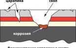
Helicing knot. Side frame connection knot with a wheel pair in a truck rail freight car
Node articulation of the brunt LIAZ-621321 bus - part 1
HNGK HNGK 19.5 Junction is designed for a flexible connection to a single buse body. The node allows you to change the mutual position of the buses sections relative to each other in three planes (Fig. 1.28).
On the simplest kinematic scheme (Fig. 14.2), the main elements of the articulation node are shown: a rotary device consisting of the upper case b, the lower body 3 and the rolling bearing 7; Damping device 4, average frame 8; Sylphons 11, platform 5. Control, alarm and diagnostics are carried out using electronic block Management, which receives information about the speed and direction of movement, on the corner and the rate of change of the angle of folding. The general appearance of the articulation node is shown in Fig. 14.3.
The rotary device, which is essentially large bearing, consists of the upper case 1 (Fig. 14.4), the lower case 44 and the bearing. The lower case 44 of the rotary device is rigidly fixed on the transverse beam 8 of the rear section of the bus by self-adjustable bolts 9. The crossbar 8 is fixed in turn on the buse base frame. The top housing 1 for hinged - rubber-metal bearings 32 is connected with a transverse beam 2 of the front selection of the bus. The rotary device provides the desired angle in the horizontal plane between the bus sections when turning (folding). The hinge joint of the top case with the front axle of the bus by means of ripberometallic bearings 32 compensates for the change of the road profile in the longitudinal direction (bend angle), providing a turn (in small limits) of the rear section of the bus relative to the front in the vertical plane. The same rubberometallic bearings 32 at the expense of own deformations also provide compensation of road irregularities in the transverse direction (spinning angle).
The rubberometallic bearing 32 is installed in the tide of the upper case and is fixed from the longitudinal displacement of the locking rings 30. The rubberometallic bearing shaft is relying on its ends with its ends on the front-section brackets, which have hook ends. The mount is carried out with the help of pins 5, bolts 3 and nuts b.
The damping device is used to counteract the spontaneous folding of the bus, which, given the rear placement of the engine ("pushing" scheme), such factors such as the state of the road (for example, icing), uneven
loading and others. The damping device consists of two hydraulic cylinders 12 (Fig. 14.3), articulated with a rotary device hinged. In each cylinder there is a water tube 3 (Fig. 14.5), according to which working fluid Purses from one cylinder cavity to another.
The principle of the damping device is that when turning the bus, the liquid flows from one cylinder cavity to another through the bypass tube 3 and
Proportional valve 5 (or 12). The valve has a certain resistance of the fluid flow (throttling) than and is provided by the damping effect of the device. Proportional electromagnetic valves 5 and 12 adjust the pressure in a particular cavity of the hydraulic cylinder, and the regulation is carried out independently in each cylinder. The valves are controlled by the electronic unit of the joint assembly. To track the pressure in the hydraulic cylinders, the pressure sensors b and 13 are installed on them.
The damping device also has an emergency damping valve 14, which functions when refusal (electronic control unit, proportional valve, emergency power outage, etc.) and ensures that the minimum degree of damping is constant.
The average frame B (Fig. 14.3) serves to attach rubberometallic bellows that closing the space between the buses sections.
At the bottom of the middle frame is attached to the main shaft (see Fig. 14.4, pos. 42 and 43). In the upper part of the middle frame, a stabilizer 3 was installed (Fig. 14.3) and power engine capacity 2.
The average frame consists of two profiles of a special cross section, which are top-bottomed and below the rails. On the side parts of the frame installed supporting supports 7 (Fig. 14.3) with rollers 10.
Patent owners RU 2412066:
The invention relates to the field of mechanical engineering, namely to the connection of two hinged-articulated sections vehicle. The articulation node includes two links, which are connected together with the possibility of rotation around the protracted device acting as a vertical axis. The first joint link includes a U-shaped, similar to Zev, a hole for capturing the second joint link in the vertical axis area. Slip devices operating between articular links are provided at least in the axial direction. The structure of the protracted device includes a means of displacement displacement. The second joint link includes two elements of articulation links, which individually with screws are attached to the frame of the vehicle section. Slip devices are provided to ensure the movement of two links of the articulation assembly relative to each other. To ensure long-term operation of moving devices, it is necessary that the joints of the joints are between which the sliding devices are located, moved relative to each other with a zero gap. The reliability and durability of the vehicle articulation node is achieved. 23 Z.P. F-ls, 4 il.
The present invention relates to a compound of two articulated vehicle sections, such as the articulated vehicle, which includes the articulation node.
An articulated vehicle is known, which may consist of several sections. Sections of such an articulated vehicle are connected with the help of the articulation node. The articulation assembly is equipped with a flexible corrugated fence, the transition of passengers from one vehicle section to another is carried out by aisle.
It is known that articulated trains or articulated vehicles are subject to incommensurable to large offsets. Such an articulation should be able to absorb the displacement during the roll, longitudinal displacements and displacement during bending. In this case, the term articulation means a hinged connection of two sections of the vehicle. Under the roll means a displacement, in which two vehicle sections turn relative to each other and relative to the longitudinal axis. The displacement of bending occurs when two sections of the articulated vehicle fit into the curve when turning, and the longitudinal displacement occurs when such an articulated train moves alonggram and pit.
In order to fit into curves when turning and, for example, in order to move the pits, a well-known hub of the articulation of the vehicle sections includes a hinged joint and the articulation of the horizontal axis. The articulation of the horizontal axis provides a displacement of two hinged-artized sections of the vehicle relative to each other and relative to the axis passing across the longitudinal axis of the vehicle. Usually bearings with a horizontal axis provided for this purpose are made of metal with rubber tabs.
So far, it was assumed that due to the internally inherent elasticity of the running part of the relevant sections of the vehicle, the roll is quenched by the most chassis. This is partly true, because the roll angle is no more than 3 °. However, it was found out that even with such very small roll angles torque, which act on the hinge and / or on the running part, are up to 35 kNm. Thus, it is impossible to exclude damage to the chassis and / or articulation. In particular, the articulation node, which allows the articulated train to fit into the curve when turning, perceives heavy loads. This was reflected in the fact that in the field of the joint assembly, the rolling bearings are installed, and these bearings, in the end, not only transmit the load on the saddle on the wagons section, but may also be transmitted and efforts arising during Found the explanation of the rolls.
Thus, in document DE 102006050210.8, a method for connecting an articulation node, which is the composite section of the hinge, with one vehicle section to transmit roll and longitudinal displacement. This means that the hinge includes two hinge elements, namely the articulation node and one additional hinge element that transmit roll and longitudinal displacement. Since such a hinge assembly allows you to transmit a longitudinal displacement and roll, you can exclude the loads, both on the running part of both sections of the vehicle and the hinge itself. This is explained by the fact that only the load on the saddle and the tensile force, as well as a short torque caused by a roll, which is less than 10 kNm should be transmitted through the articulation node. Until now, the junction assembly included the rolling bearings of significant sizes. Considering that the use of a hinge design slightly reduces the forces acting on the hinge support, other bearings can be used, which are much cheaper than the rolling bearings of very large sizes used to date.
In addition, a hinged support is known from the document DE 1133749 with two forces superimposed on each other, while the carrier plate of another part of the articulation node is located. To connect the corresponding plug with a carrier plate, a bolts with through threads are provided. A carrier plate is located between the legs of one of the two forks, which is used as an adjusting washer acting as a stubborn washer. When you stop in the stubborn washers, the tensile legs are stretched. As a result, the stubborn washers are loaded unevenly, since the legs of the fork are slightly narrowed when the threaded bolt is stretched, since the forks are made in addition and consist of one part. This leads to the fact that the edges are pressed into the stubborn washers, which leads to fast wear Bearings.
In accordance with the present invention, the articulation node includes two links, which are connected together with the possibility of turning around the protracted device acting as a vertical axis, while the first joint link includes a U-shaped similar to Zev Hole to capture the other, the second joint link In the region of the vertical axis, the sliding devices acting between the joint links are provided in at least in the axial direction (referred to the direction of the joint axis), and the joint device includes a means of ensuring the joint link displacement, to the composition of one articulation link There are two elements of articulation links, which individually with screws are attached to the frame of the vehicle section. Slip devices are provided to ensure the movement of two links of the articulation assembly relative to each other. To ensure long-term operation of moving devices, it is necessary that the joints of the joints are between which the sliding devices are located, moved relative to each other with a zero gap. This means that with an independent attachment of the articulation link elements, you can adjust the position of the sliding devices and provide zero clearance. On the other hand, with an independent attachment of the elements of the joint link elements, the risk is reduced to drag the elements of one articulation link relative to another joint link. The reason is that the first and second joint links are connected together and are associated with the corresponding vehicle sections. The presence of long openings on the frame of vehicles provides certain variability.
In accordance with the present invention, to ensure a zero clearance, a means of ensuring the connection link displacement is included. It is clear that even if the sliding devices are wearing over time, it is constantly a landing with a zero gap is constantly ensured.
In particular, to perform a displacement in accordance with a preferred embodiment of the present invention, it is envisaged that the axial sleeve and lockout includes a protracted device, while the said axial sleeve is connected to the locknut preferably by means of a bolt, and two articulation links are shifted along one threaded bolt under the action Springs. The axial sleeve acts as an axis of the articulation assembly, around which two articulation links are moved relative to each other. In accordance with another feature of the present invention to provide an appropriate pressure on the joint links in the axial direction on the axial sleeve, a bin is made, acting on one first link link, and a scurrical nut, which acts on the other side of this first joint link.
In accordance with another feature of the present invention, a bin is made on the inner surface of the axial sleeve, which resumes the head of the threaded bolt. As a result, the protracted device is flush with the surface of the first articulation link.
In accordance with the first embodiment of the present invention on top and bottom of the second joint link, in the area of \u200b\u200bthe protracted device, a ring flow under the stubborn washer was made, while the mentioned thrust washer is pressed to the first joint link, at least one, and in accordance with the preferred example The implementation of the present invention is three (to provide a balance) with spring systems that are evenly distributed around the circle, and between the thrust washer and the first link of the articulation is a sliding device. In principle, two joint links always constitute a compound by means of a spring-loaded stubborn washer, which puts pressure on the sliding device, for example, on a ring gasket made, for example, from Teflon. That is, the present device is self-regulating, which means that the wear of the annular gasket is compensated by a protracted device and, in particular, the spring system. As already explained, the annular gasket puts pressure on the first joint link with the spring system. In this case, the composition of the spring system includes several circumferential assemblies of plated springs, each of which, in particular, is sent to the guide bolt. As a result, the ring gasket that performs the role of a sliding device is evenly loaded with a thrust washer and, thus, has uniform pressure on the first joint link. The assembly of plate springs is located in the cavity located under the stubborn washer. The guide bolt, located in the cavity, serves as a guide for assembling the plate springs and prevents the rotation of the stubborn washer.
The sliding device made in the form of an annular gasket transmits an effort acting in the direction of the axis of the protracted device. Essentially, these forces are rotating moments arising from the load per seat, as well as small torque arising from the roll. To transfer braking and acceleration forces between the axial sleeve and the second rolling link, the slip bush is set. This sliding sleeve can be made from the same material as the ring gasket that performs the role of the sliding device.
The second embodiment of the present invention is characterized by the fact that the spring system is located on the inner surface of the axial sleeve between the threaded bolt and the broth. The spring system, which, in particular, is made in the form of assembly of plate springs, constantly fit to the second joint link in the area of \u200b\u200bsuch a yawn hole of the first joint link. In this context, it is necessary to note the following.
A similar zev u-shaped hole is formed when connecting the upper and lower elements of the first articulation link. These two elements of the articulation link are attached to the frame of the chassis, at the same time the bearing is first assembled. This directly leads to the fact that to obtain a zero gap between two articulation links as a threaded bolt and the assembly of plate springs must overcome their own elasticity of the first joint link, which is a particularly difficult task, if a hinge compound with a frame that makes the first joint elements, It occurs through a rigid connection. This is the advantage of the first embodiment of the present invention over the second, since the rigidity of the first articulation link does not affect the landing with a zero gap.
In accordance with the second embodiment of the present invention, as well as in accordance with the first, the sliding devices are provided between the joint links, made in the form of ring gaskets, and the movable sleeve is also provided between the axial sleeve and the second joint link.
In accordance with the third embodiment of the present invention, two, so-called spherical supports are provided as a slide device. Such a spherical support is characterized by the fact that it is performed in the form of a sliding support and includes two liners with arc-shaped sliding surfaces. The arc-shaped contour of the liners of bearings contributes to the absorption of forces in both radial and axial directions. It is also important that such a spherical support is capable of providing the work of two components of parts at a zero gap between them.
To ensure a landing with a zero gap, two liners of two sliding bearings, which are converted to each other in the axial direction, perceive the effects of the springs so that self-regulation of spherical support is ensured, that is, the wear of two adjacent liners of each spherical support is compensated by the power of the springs.
To ensure adjustment of the sliding bearing, which perceives the strength of the springs, is installed on a free landing, and the other sliding bearing is set to a dense landing. To prevent the bearing mounted on a free landing, a prismatic key is used.
It is also provided that one spherical support liner rests on one joint link, and the other insert of a spherical support rests on another joint link. Tarbed springs, which, in particular, form the sprocket assembly, act on two inserts of a spherical support, and the mentioned liners are located opposite each other along the axis, that is, along the axis of rotation, and thus pressing the spherical support on the axis; Some signs of wear during operation are compensated by an arcuate profile.
In all embodiments, the implementation of the present invention is prevented by turning the axial sleeve relative to the first joint link, the lock nut also applies. Only the second joint link can be rotated relative to the first articulation link.
With the help of the following drawings, the present invention is explained in more detail.
Figure 1 presents the main drawing of the articulation of two sections of the vehicle.
Figure 2 presents the articulation node for the first example of the implementation of the present invention.
FIG. 3 shows the articulation node for the second embodiment of the present invention.
Figure 4 presents the articulation node in the third example of the implementation of the present invention.
Figure 1 shows the articulation of 1 two sections of the vehicle 2, 3. The articulation 1 includes, in particular, the articulation unit 10 and the longitudinal rolling bearings / roll 30 mounted between the articulation node and the vehicle section 2. The articulation unit 10 is associated with a section 3 of the vehicle through frame 40, dampers 50, installed between the joint node 10 and the frame 40. The articulation node turns around the axis 60.
The present invention proposes a joint node 10. In the two versions presented in FIGS. 2 and 3, the articulation unit 10 includes the first joint link 11 and the second joint link 12. In the first joint link 11 there is a U-shaped similar to Zev hole 13, in which Other, second joint links 12 is inserted. The first joint link 11 includes two elements of the joint link 11a and 11b, each of which is attached to the frame with 40 screws (not shown).
To connect two links of the joints 11, 12, a protracted device 20 is provided, which also forms the axis of rotation and articulation. The composition of the protracted device 20 includes the axial sleeve 21 and lockout 22, while the mentioned axis sleeve 21 is associated with a lock nut 22 by means of a threaded bolt 23. Like the axial sleeve 21 and the locknight 22 are equipped with a palate 21a, 22a, which is both in the tapes and The axial sleeve rests into the lower and upper sides of the joint link 11, as can be seen in FIG. 2 and figure 3. Both the axial sleeve 21 and the locking tip 22 are fixedly attached to the joint link 11 pins 21b, 22b, which guarantees the movement of only two joint links 11, 12 relative to each other.
To connect a threaded bolt 23 with a locknut 22 on the inner surface of the axial sleeve, a bin 21c is made in which the head of the threaded bolt 23 is removed. Between the front side of the second joint link 12 and the axial sleeve 21 is installed sliding sleeve 24. This sliding sleeve 24 transfers the forces arising from Acceleration and braking when the vehicle is rolling from the place and slows down.
An example of the implementation of the present invention, presented in FIG. 2, provides both the transmission of the load per seat and a small torque arising during the roll and turn two joints of the joints 11, 12.
In the second joint link 12, a ring flow 14 was performed. In this ring flow 14 installed a stubborn washer 15. An annular gasket 16 is stacked on a thrust washer, for example, from teflon, which acts as a sliding device and which is fixed on the inner surface of such a zev zev Articulations 11. Under the stubborn washer 15, a somewhat distributed in the circumference of the grooves 17 is established for individual assemblies of plate springs 18. Through these assemblies of plate springs 18, which are sent to the guide bolt 19, the stubborn washer 15 together with the ring gasket lying on it, presses to the annular 16 Helicing link 11, as shown in figure 2.
Thus, using assemblies of plate springs, a landing with a zero gap of two joint links 11, 12 is always ensured, and this planting provides twist of two joint links relative to each other.
The device made in accordance with an embodiment of the present invention shown in FIG. 3 differs from the device made in accordance with an embodiment of the present invention shown in figure 2, the fact that the displacement is ensured by assembling plate springs 27 located between the threaded head. bolt 23 and border 21c.
In principle, the device made in accordance with an embodiment of the present invention shown in FIG. 4, differs from the device made in accordance with an embodiment of the present invention, presented in FIG. 2 and 3, the fact that two, so-called, Spherical supports 25, which are superimposed on each other along the axis of the hinge support, that is, in the direction of the axis of rotation of the hinge support. Thus, two joints of the joints 11 and 12 form a hinge, which turns on two spherical supports 25. In particular, in the joint link 12, a hole 35 was performed in which a hinge support is inserted. In the area of \u200b\u200bthe opening 35 of the joint link 12 there is a ring duct 12a. Inserts 25a, 125a spherical support 25, 125 rely on the wall of the groove 12a. The corresponding liners 25b, 125b each of the spherical supports 25, 125 are based on another joint link 11, which is clear from figure 4.
In the hinge compound of two links of the joints 11 and 12, a threaded bolt 23 is provided, as well as the axial sleeve 21 and lockout 22, while the said axial sleeve 21 and said locknight 22 are fastened together with a threaded bolt 23. In the area of \u200b\u200bthe groove 12a between the axial sleeve 21 and locknut 22 A space called the spring chamber 27 is formed, into which the assembly of plate springs 37 is placed as a spring system. The two liner 125a, 125b installed on the free landing of the spherical support 125 are located in such a way that the assembly of plate springs affects the liner 125a, and the liner 125a constantly presses On the corresponding liners 125b under the action of assembling plate springs 37. As a result, the gap formed by wear on the contact surface of the two liners 125a and 125b is compensated. The spherical support installed on a free landing remains stationary, because From rotation, it prevents prismatic key 38.
Figures 2, 3 and 4 identical positions are indicated by the same numbers.
1. The articulation (1) of two hinged articulated sections of the vehicle (2, 3), for example, the articulated vehicle, which includes the articulation node (10), the composition of the mentioned joint node (10) consists of two joints (11, 12 ), which are connected together with the possibility of rotation around the protracted device (20) acting as the vertical axis, said first joint link (11) includes a U-shaped, similar to Zev hole (13) to capture another second joint link (12) in the region The vertical axis, the sliding device (16), provided between the joints links (11, 12), act, at least in the axial direction, the composition of the mentioned protracted device (20) includes means to ensure the displacement of the joint links (11, 12), At the same time, one joint link (11) consists of two elements of the joint link (11a, 11b), each of which is attached separately to the frame (40) of the vehicle section (3) with screws.
2. The articulation according to claim 1, characterized in that the axial sleeve (21) and locking (22) include the composition of the protracted device (20), while the said axis sleeve (21) is connected to said locknut (22).
3. The articulation according to claim 1, characterized in that the axial sleeve (21) is connected to the lock nut (22) with a threaded bolt (23), while two articulation links (11, 12) are shifted under the action of the spring system (18, 27) pressed by the mentioned threaded bolt (23).
4. The articulation according to any one of claims 1 to 3, characterized in that the axial sleeve (21) is made with a collar (21a).
5. The articulation according to any one of claims 1 to 3, characterized in that the locknight (22) is made with a collar (22a).
6. The articulation according to any one of claims 1 to 3, characterized in that the axial sleeve (21) is made with the collar (21c) on the inner surface under the head of the threaded bolt (23).
7. The articulation according to any one of claims 1 to 3, characterized in that on top and bottom of the second joint link (12), an annular flow (14) was made in the field of a protracted device (20) under the stubborn washer (15), said stubborn washer (15 ) It is pressed to the first joint link (11), at least one, and in accordance with the preferred embodiment of the present invention, three (to provide a balance) with spring systems (18), which are evenly distributed around the circle, while between the thrust washer mentioned ( 15) and the mentioned first joint link (11) installed a sliding device (16).
8. The articulation of claim 7, characterized in that the sliding device (16) is made in the form of a ring gasket.
9. The articulation of claim 7, characterized in that the spring system (18) includes several assemblies of plate springs located around the circle.
10. The articulation of claim 9, characterized in that the assembly of plate springs (18) is sent to the guide bolt (19).
11. The articulation of claim 9, characterized in that the assembly of plate springs (18) is placed in the cavity (17) located under the stubborn washer (15).
12. The articulation according to claim 1, characterized in that between the axial sleeve (21) and the second joint link (12) there is a sliding sleeve (24).
13. The articulation according to any one of claims 1 to 3, characterized in that the spring device (27) is located between the threaded bolt (23) and the border (21c).
14. The articulation according to any one of claims 1 to 3, characterized in that the spring device (27) is made in the form of assembling plate springs.
15. The articulation according to any one of claims 1 to 3, characterized in that there are sliding devices (16), made in the form of ring gaskets between the joints of the articulation (11, 12).
16. The articulation according to any one of claims 1 to 3, characterized in that there is a sliding sleeve (24) between the axial sleeve (21) and the second joint link (12).
17. The articulation according to any one of claims 1 to 3, characterized in that the axial sleeve is attached to the first joint link (11) without the possibility of rotation (21a).
18. The articulation according to any one of claims 1 to 3, characterized in that the lock nut is attached to the first joint link (11) without the possibility of rotation.
19. The articulation according to any one of claims 1 to 3, characterized in that the sliding devices (16) include at least two spherical supports (25, 125).
20. The articulation of claim 19, characterized in that the spherical support (25) is made in the form of a sliding bearing.
21. The articulation of claim 19, characterized in that the spherical support includes two liners (25a, 25b), and the composition of the two mentioned liners includes arcuate conjugate sliding surfaces.
The trolley is the chassis of the car through which the interaction of the car and the path is carried out, as well as directional movement along the railway (Fig. 3.0).
The trolley in accordance with the pattern consists of: two wheeled steam 1 with zapor nodes; two side frames 2; Superstar beam 3; Spring hanging 4 with the central location of spring sets in the side frames of the trolley; Brake lever gear 5 with one-sided pressing pads on wheels and suspended triangers. The articulation of the side frame with wheel pairs is carried out through a replaceable wear-resistant polymer insertion 6 and adapter 7. When the car equipment is automatic regulator of braking modes on one of the carts rolled under the car, the support beam is installed. 8. The cart is equipped with elastic spaces; 9 devices excluding the possibility of the exit of wheel steam from the beam opening of the side frames; Device 12 for the directional removal of the pads from the wheels when the brake is released; Device 13 for removing static electricity from the rail to the rail; Skvornna 14. In addition, the trolley provides for safety devices from the fall of parts on the path of the triangels, tightening, check, axes (rollers) of the brake lever transmission in the case of sudden failures and when unloading to the carriager.
Fig. 1.5
The side frame (Fig. 0.0) is intended for perception of loads transmitted from the body of the car, transmitting them to the wheeled pairs, as well as to accommodate the spring kit.
The side frame is an casting, in the middle part of which is located the opening of the weight of the spring kit, and along the terminal parts, the occasional openings d to the installation of wheeled steam.
The lower part of the spring opening forms the support plate E with the sides placed on it and the browns for fixing the springs of the spring kit. On the vertical walls of the spring opening, platforms are made to which friction strips 1. The stops are used to restrict the transverse movements of friction wedges.
From the inside of the side frame, the support plate E enters the safety shelves, which are supports for the tips of the triangels in the event of a breakdown of suspensions, which are suspended to the brackets of the side frame. Polymer wear-resistant sleeves are installed in the brackets 3. The shelves and with oval holes serve as supports for the vehicle beam.
At the bottom of the beam opening on the side frame there are brackets to with holes for fastening a device that protects the wheeled pairs from the exit from the occasional opening with extreme situations.

Fig. 3.1.
The surmant beam (Fig. 3.1) is a battle-section casting and serves to transmit the load on the spring kits and the elastic-frictional communication of the side frames of the trolley. Loads for friction wedges of quenching of the oscillations of the spring kit are transmitted through inclined sites located in special pockets made at the ends of the superior beam. On the upper belt of the outstanding beam are located: a spying place for Friday of the Wagon, supporting areas with threaded holes for the installation of the SBUs. On the lower support surfaces of the outstanding beam, ribs are made, which are fixed by the outer springs of the spring kit. On the side wall of the outstanding beam in the middle part are tides to install the holder dead point 1, fixed with rivets 2. The wear-resistant element-bowl 3 with a hardness of 255-341 HB is installed in the spying place. To prevent bowls from the fallout, a pressure limit was introduced with a cleaner flush in four places with the provision of a gap between the surfacing and a bowl of at least 0.2 mm. Junction of the side frame with wheel pairs. The side frame is installed on the wheeled pairs through the replaceable wear-resistant polymer inserts and special adapters. Devices exclude the possibility of the exit of wheel steam from the beam openings of the side frames during the collisions of the wagons and other operational situations.
V. Orlov, City Transport Engineer, Minsk
In August 1997, the bus station of the MAZ replenished the released family new model - articulated highly large capacity that received the designation 105. On the city route, the first such bus came out in the spring of 1999. The bus is designed by the "pulling" scheme - with the leading middle bridge. The design has noticeable distinctive feature: The engine located in the "tractor" (first section) is set vertically on the left. In addition to the fact that there is no need for a complex and expensive housing assembly (antislement), the coupling mass increased, i.e. the permeability and stability improved, and a coupling device based on a spherical hinge provides sections three degrees of freedom. The adopted layout allowed to lower the floor level of the cabin to 600 mm along the entire length, and the doorways have one step. In 2002, at the Moscow motor show, Likinsky bus plant presented the articulated Liaz-6212 bus with the location of the engine in the database (horizontally). Currently, the bus is released serially. The mechanism of its antislement was developed by Liaz designers independently. It should be noted that our own developments of such nodes are only a few companies in the world. In 2005, an experienced low-voltage "harmonica" mod was collected. 6213 (with a purchase node of the anti-skid), and at present, the prototypes of the bus undergo operational tests.
Destinations of approval today's hinge and articulated bus Lviv bus factory "City" LAZ-20 which comes and in the trolleybus version. A self-developed body and scheme of its painting are successful. The length of the machine exceeding the "standard" 18 m, puts it in a number of the newest "accordions" of world-renowned manufacturers - EVObus (mod. Capacity) and Neoman (GXL).
In 1993, the plant from Likino-Dullyvo presented the urban articulated Liaz-6220 large capacity bus. Factory designers independently have developed a buses (articulated) signed in the CIS (articulated), and the new, rear-engine layout on the so-called "pushing" scheme. Studying the conditions for ensuring sustainability and manageability fundamentally new car And the development of the appropriate mechanisms, Liaza designers led together with the specialists of the Moscow Auto Equipment Institute (MMU MAMI). Their conclusions did not contradict the experience of colleagues from industrialized countries (there the articulated buses appeared earlier), especially considering that for buses of such a sizes, these tasks and in the West are not solved finally.
The junction of the sections of sections with the "pushing" scheme has only two degrees of freedom (i.e. it does not allow them to be spinning relative to each other when driving on uneven roads or damage to the elements of the pneumatic suspension of one side), which leads to additional loads on the body and the articulation that reduces their resource. It was found: to prevent "folding" sections of the bus in turns (and when driving on a slippery road) in the design of the rear-engine "articians" requires a special device. The capabilities of the ABS brakes that helps to avoid folding when braking, for an articulated bus with a drive on the third bridge is not enough. Installation in the Hydraulic (unregulated) demipment unit as a whole ensures the stability of the bus movement, the resulting transverse oscillations of the sections and prevents them from a split. At the same time, the danger of folding remained. To prevent or decrease it to a safe size, a damper was used with an alternating diameter spool valve. Run ahead, let's say that the task of the maximum was littering the work of the damper with angular speed, the magnitude of the rotation (and bounce) of the controlled wheels, taking into account the clutch coefficient with the road. In addition, an end sensor was needed, at the angle of folding sections of 45º (maximum permissible for different designs of the node) the feeding command to the antisleam system and thereby preventing a further increase in the angle of rotation. The basis of the antislement device is the double-acting hydraulic cylinders, which are also called hydraulic shock absorbers with changing resistance. However, a special electronic unit was required to regulate their resistance.
It remains to be said that the cost of the antisode system or ensuring the stability of the rear-wheel drive bus, which is a complex electron hydraulic device, comparable to the cost modern engine and hydromechanical gearbox!
In the articulated buses of industrialized countries having a "pushing" scheme, a more complex mechanism of anti-skid of sections was used. In the mentioned mod. O305G The device consisted of two angles of the angle of rotation built into the steering mechanism, and chokes with solenoid valves embedded in pipelines connecting the hydraulic cylinders (two for each section of the bus). With an increase in the angle of folding, the chokes reinforced the resistance of the flow of fluid between the hydraulic cylinders. If the angle of folding exceeded 45º, electromagnetic valves Blocked fluid flow, locking the hydraulic cylinders. The onboard electronic system compared the speed of rotation of the wheels of the middle and the rear axes, turning off the supply of fuel when the permissible values \u200b\u200bof the relationship between them are exceeded. All wheels were equipped with lateral slip sensors, the signal of which caused the corresponding control effects on the anti-skid mechanism. Howbeit, domestic development The anti-skip assembly and its control system has become a real success of Liaza.
What is the popularity of particularly large urban buses with the pushing rear section? Earlier - with the possibility of their unification with single city buses and a decrease in the noise level of the engine in the cabin, now - with a decrease in the height of the floor, because under the floor there is no power plant. In other words, chief flaw The articulated buses with the horizontal arrangement of the engine in the database and the average leading axis (schemes, until recently considered classical), is currently associated with relatively high floors and noise in the cabin with such a layout. In general, modern articulated buses differ in wheel drive and engine location (horizontal or vertical).
Also known to the articulated buses with the engine located in the rear and the average leading axis (mod. SG24OH MAN, mod. 260-SH170 Magirus-Deutz, some others), and in some cases with leading rear and middle bridges (or front and medium Installing a uniaxial section in front of a two-axle back-engine bus). At the same time, the torque from the engine is transmitted by a multisective cardan shaft through the articulation node on the leading axis of the front section. As noted by MSTU Mami experts, the transfer of torque through the place of articulation in this case, with leading rear wheels The front section (middle bridge) significantly complicates the bus construction. Designers were required to a thoroughly to work out the location of the cardan shaft through the articulation node. This bus is still needed by a more complete load of the average (leading) axis, for which in some cases it was necessary to separate the gearbox from the engine, setting it in front of the bus. In addition, the use of such a design led to an unenimate with the base (single) model.
The advantage of buses with the average leading axis and the "rear" engine is the lack of a folding mechanism.
Evobus and Neoman in 2007, almost simultaneously presented the latest articulated buses. Their main feature has become non-standard for two-section design. Length, in turn, determined:
The manufacture of buses according to the scheme "single" + "trailer" in the form of a chassis of a 15-meter "three-axis";
the need to use in the 2nd section of two axes;
The ability to use both (3rd and 4th) leading bridge "trailer", since the 4th axis is a twirling.
At the same time, the worst layout of the "feed" part of the Capacity buses - 2 steps of the 4th door, I think, will make passengers remember the proverb: "Not all that is gold, which shines." The "highlight" of the same GXL from Neoman is a transparent corrugation over the housing of the articulation. What will Irisbus answer?
As for the overseas bus markets, although it is believed that "harmonica" appeared in the United States in the 1930s, today on the European continent their park and popularity is much higher.
It has already been noted that among the various layout schemes of the articulated buses, the greatest distribution, despite all the difficulties, received the rear-engine scheme just because of the possibility of lowering the height of the floor of the cabin. The "articraft" performed on the "pushing" scheme crossed, but did they achieve a low floor height of the cabin? And how is this provided in the considered models?
In MAZ-105, it was possible to provide the same height of the floor (600 mm) in the entire length of the salon if there is a step at each input.
Buses with stepless entrances are called low-profile. Ensure the lack of steps in all doors in "accordions" is much more complicated than in single models. So, in LIAZ-6213 and "City" LAZ-20 A292 There are no steps only at the first and second doors (in the front section). Why? In the zone of the latter door, the height of the floor is increased, in order to place the main gear and the engine, and in the third door zone, the floor height depends on the location under the gear of the mechanisms of the anti-sysk device.
"Partial low-fullness" is characteristic not only for the equipment of the CIS. In the newest "accordion" Capacity from Evobus from the back door to the salon lead ... two steps. To exclude such a "staircase", the fourth door of the articulated buses of European manufacturers (Neoplan, Setra, Volvo) was previously "sewn".
To ensure a stepless entrance to the second section or reduce the number of steps to one, some bus accidents, in particular irisbus, the individual elements of the anti-skid mechanism are placed over the articulation node corrugation (in this case, part of the roof is towers).
It remains to add that in articulated trolleybuses, a stepless input can be provided even when the traction engine is located in the front section, since the dimensions are small, especially if the AC motor. So, in the manufactured plant "Belkommunmash" (Belarus), in the spring of 1998, the "harmonic" mod. 333 In the front section (opposite the second door), not only the electric motor was installed, but also auxiliary diesel generator set (for movement without meals "from wires"). In this model, the steps were absent in all four doors, and a cumulative platform was arranged opposite the third. Known and trolleybuses with accommodation traction electric motor In the rear section and the use of an anti-skid node.
LIAZ-6212.
Rear, in the 2nd section, with the drive to the rear axle |
|||
| Engine | Renault Om906. | Catepillar. | Deutz / Man. |
| Transmission (number of steps and type) | Praga / ZF / VOITH (5P / 6P / 3A) | Voith (3a) | ZF (6A) |
| Main bridge | MAZ | Raba. | Zf. |
| Floor location salon | Reduced, at the height of one step along the entire length | In the front section - stepless | |
| Release volumes, units * | 2003 - 47 2004 - 123 2005 - 115 2006 - 192 2007 - 202 |
2003 - 50 2004 - 269 2005 - 69 2006 - 34 2007 - 376 |
n. d. |
| * According to OJSC ASM-Holding. | |||


Union of the SovietSoSInistical Principal A 1 O 51) 5 in 61 p 15 10 Consistent Committee of Inventions and Opening Merities GKST USSR Description of the Invention A Second Certificate (54) Highlight Highlights of the Side Frame of Trollets with Trucks of Wheel Couples (57) The invention relates to railway transport and allows you to improve the driving quality of the trolley by reducing the power influence on the trolley and the path. The device contains an intermediate support element 3, which has finite elasticity (flexibility) in the vertical direction, the convex-concave form of which provides the possibility of pendulum oscillations of the lateral frame 1 relative to the case of the Oaksus 2 in the vertical transverse plane, the possibility of relative mixing (shift or rotation) for any of two Supporting surfaces and the possibility of increasing the mobility of the cart in horizontal PLS. 3 and, .1585194 The invention relates to railway transport and concerns the design of the cargo wagon truck. The scene of the invention is to improve the driving values \u200b\u200bby reducing the power influence on the trolley and the path, in FIG. 1 shows the articulation device, front view; FIG, 2 - the same, top view; FIG. 3 - Support element. Dead-in-theerat's suspension monitors 1 with letters 2 of wheel steam contains 10 ROMODUBERY PUBLIC ELEMENT 3, butted with a gap to a flat circular buckle of 4 letters bounded with two stons concentric with her side ribs and - protrusions 5. Claim 5 Side frame of the side frame of the trolley of wheelbase wheeled pauses, containing a convex reference element installed in the cycular opening, a convex support element, limited by protrusions on the horizontal leak surface, characterized in that, with the aim of improving challenges Trolleys due to a reduction in the power influence on the trolley and the path, the support element is set with a gap relative to the protrusions, is made in terms of disk, and its convex surface is formed by the top flat horizontal section and the ring spherical plot conjugate with it, while the specified surface frame surface is made horizontal. The support element 3 is made in the form of a circular plate, the upper support surface of which has a spherical shape 6, cut off by the horizontal plane 7, and the lower row surface is a flat ring. When actions in the horizontal transverse plane of the dynamic forces, transmitted from the carriage body to the cart and deflecting the trolley , there are relative movements of the side frame and traces. Due to the flat-grudic form of the support element 3, the pendulum oscillations of the side frame relative to the housing, the letters will begin only after overcoming a certain holding torque (reactive force), the value of which depends on the size (diameter) of the flat part of this surface, that is, there is a decrease in the rigidity of the perception of the lateral forces. In addition, the possibility of relative movement both along the upper and the lower support surfaces of the support element is ensured than the decrease in the friction forces between the side frame and the Buxeria.Niashsk NT, Sasta VITER M TECRRA A. Kravchuk Circulation 397 of the Committee of the Winter Oscav, W - 35, Rau affair Pat
Request
4483715, 27.07.1988
All-Union Research Institute of Carriage
Kuzmich Leonid Dmitrievich, Zavt Boris Samuilovich, Sychev Valery Alekseevich, Kashkin Alexey Ilyin, Doublechalov Vyacheslav Aleksandrovich, Gailer Moses Petrovich, Barbashov Valentin Mikhailovich
MPK / Tags
Link code
Device articulation of a side frame of a trolley with wheelsets
Related patents
Pictures depicted tiles with a side frame of a 10growted car carriage in the cross section along the horizontal axis of the wheel pair (two embodiments of the node). When there are two versions of the articulation assembly with one restricted stitch (on the section to the right of the axis) or the two restrictive protrusions (navigation to the left of the axis) . Troops 1 troops with a side frame of 2 trolleys contained on the wheels of the wheel pair 3 bearings 4, installed in the box 1, having 1 TSE jaws 5 with stops 6, covering the heading guides of the side frame 2 of the trolley, and the jaws are 5 Synod with vertical grooves 8, in which they enter Vertical restrictions 9, made on guides of 725 bottom opening with gaps A, B, exceeding ...
More than 5, 6 and 7, 8.Found ends of the levers 5, 6 and 7, 8 are pairwise interconnected by themselves 9 and 10, at the ends of which the elements 11 of rotation are installed, the rolling bearings are installed, located at a distance exceeding the buccular opening width of the side frame 12, The load perceived unit 13 is installed in the connection site of the link2 from. Defense works as follows. The lever transmission 1 of the setting of the side frame 12 in the belling opening of the side frame 12, the elements 11 of rotation are set to the horizontal support surface of the base 14 in such a way that the axis 9 and 10 rested into the jaw guides 15 and 16, after that, on the Georgovosiming unit 13, install hard -No element 17, by means of which the variable ...
For spring springs, and columns, where the installation of platforms and guides for wedges of the oscillation damper, as well as brackets for fastening the triangle suspensions. The specified can be performed only by manual welding, and the time-consuming zone is the zone of the occurrence, where welding works can also mainly be performed by hand. Tool and .: Observing - Improve the technologicality of the labor-intensity of the production of the side frame. The following goal is achieved by the fact that in the well-known side frame containing Rigidly interconnected upper and lower with a pallet for installing spring springs of a belt connecting 5 10 15 20 25 30 35 40 45 of their columns and inclined belts, conjugate with end parts for beks, lower ...