Idling regulator: Purpose and repair RXX. Incorrect meals on the PXX Sleeping Sensor Hope
Idling regulator is designed to provide stable work Engine in mode idling. Manages the work of RXX, which, depending on the mode loads, supplies power to bipolar stepper engine Regulator. Consider how to check the idle sensor and how to understand that the reason for floating revolutions is in the fault of the regulator.
Signs of breakdown
- (Floating turns).
- Spontaneous lifting or dropping of idle speed.
- The car stalls when the gas is discharged.
- After starting the cold engine there are no warm revolutions. In independence on the position of the throttle, to reduce the time of heating the catalyst ECU by 200-300 rpm. Raises idle speed. If the RCH is faulty, the stepper motor will not be able to adequately shift the position of the rod with a conical needle, thereby increasing the passage section of the throttle node bypass channel.
- When you turn on powerful consumers, the current turns fall either begin to float. The inclusion of the air conditioner compressor, or the combination of electrical appliances loading the generator, increases the load on the engine, which leads to a drop in the number of revolutions. Therefore, in idle mode, the ECU using the regulator increases the passage of the bypass channel, thus aligning the turnover.
Fault

Computer diagnostics
Despite the fact that in common RXH, it is customary to be called a sensor, the device is exclusively an actuating mechanism that has no feedback from the ECU. In other words, the voltage feed engine control unit sets the desired stem departure. But the ECU cannot objectively check the actual position of the rod, so the discrepancy between the desired and actual values \u200b\u200bis not fixed anywhere. This means that in the event of a sensor malfunction on dashboard Check Engine does not light up.
The self-diagnosis system can only register a few malfunctions of the RCX control circuit. Error options that are before checking the idle sensor can be determined by the diagnostic device through the OBD II connector:
- Р0505 - the error code indicates a malfunction in the control circuit;
- P0506 - the sensor is blocked, low idling;
- P1509. - Overload of the RCX control circuit;
- P1513. - closure to the land of the sensor control circuit;
- P1514. - open or closure on + 12V RCX control circuit.
Verification of the RHX Multimeter
How to check the idling sensor by a multimeter:
 in DC measurement mode, measure the voltage on the regulator connector (ignition should be turned on). No food will indicate a break in the control circuit;
- check the resistance of the stator windings in the resistance measurement mode (range - up to 200 ohms). SD has two windings, so you need to follow the correct connection of the tester terminals. In the technical documentation for the sensor installed on your car, you can find the nominal resistance of the windings. For example, for PCX 2112-1148300-02, the normal resistance is 51 ± 2 ohms, and for Pxx 2112-1148300-01 - 53 ± 5 ohms (both devices are installed on many VAZ models). If the indications of the multimeter talk about the imminent resistance approaching to infinity, it means that there is a breakdown in the winding circuit.

Connection diagram RHX VAZ 2110
It is possible to fully check the RHX only with the help of a special diagnostic equipment. But in most cases, the check by a multimeter, visual inspection and defecting after disassembly allow you to quite accurately diagnose the presence of a malfunction.
Remember that after replacing, flushing RXX need to carry out software adaptation of the sensor.
For everyone modern machines There are revolutions regulators of one type or another. One of the common species is a stepper idle regulator (hereinafter - RXX). The tester for such a regulator is a very useful thing for car services, and often - and for owners.
But I will start from afar. from connectors for such regulators. The connectors themselves are useful too, because it breaks quite often. Perhaps somewhere they are cheaper in Offline - but I somehow did not meet, and by analogy with other details, they will cost them.
The connectors came in the form of a package package, each - its details: 

The quality is excellent, the crafts themselves for a couple of pieces more, for which the seller thanks very much

crush and collect


there is an important nuance: Usually, all terminals are inserted into the connectors from the back, on the side of the sealing gum. Here - on the contrary. That is, the crimped terminal is inserted into the front connector, "wire forward". And if you click on the machine - then you need to stretch the wire through the connector outward, and then delay it already compressed back. From the rubber band, the terminal will not be able to insert.
Undoubtedly, the connectors and terminals will be useful to me in work, and not just to create this tester - unequivocally recommend.
We will continue. As a basis for the Tester RXH, I took the famous from Alexey Mikheenkov (ALMI): 
Actually, I have already collected such a tester for a long time, and quite satisfied with it, but there is a couple of nuances.
Firstly, the PCH of this type is two species, in no way distingurable, but globally different internally. Inside, they have two windings, but they can connect either 1 + 2, 3 + 4 contacts, or 1 + 4, 2 + 3 contacts. One pinout is used by GM, the second one is left. I do not remember who where. On the old tester, I hung two connectors for different systems. But I don't really like it. It was decided to put the switch.
Secondly, the author used chips / 4729, which are expensive when buying in China, and even more expensive in local stores. I bought the case at the case that, although a little more difficult in the strapping, but cheaper and similar to the functionality, although it does not correspond to neither on the pinout or on the work algorithm. But nevertheless, I decided to try - what if it turns out?

The reading of a datashet showed that the modes are a little different, but in fact - in general coincide.
4728:
6219:
Since in microcontrollers, I understand weakly, and I do not know how to program - quickly disassembled the firmware and made sure that it is used just two "extreme" modes, which means everything should earn.
Draw a new scheme: 
We divorce the fee: 
TRAVIM, PLEASE: 
We print the sticker and screw in half the Z24 housing 
Something I forgot ... Oh yeah! After all, I bought not only RXX connectors. I also bought it. and powerful currents.
Actually, neither photo will not describe in detail in detail - the details as the details. Resistors and Tinki in ribbons, switches in bag.

Is that on the switches stop a little more. Switches - into two groups of switchable contacts. The size of the housing is 8x7x5 (DHSHV), the switches of approximately 2x2x4mm. Step of 2mm legs, between rows - 2.5mm. However, the seller has a drawing on the product page. There are similar single-row (with one contact group) switches - and those and others are quite satisfied. I can not give a link to one-row - she already rubbed. But Ali is well searched for "SS12D07".
Everything else I had in stock. The tail for the crown put temporarily (however, it may be meaning), and I did not check the fee until 100% - it works at the Opolevsky RCX exactly, but from Peugeot (with the second pickup) I do not have in stock. As I check - I will definitely add a review, especially if something goes wrong.
I will also stop a little on programming chips. The author offers two options: "Normal" programmer and Avreal. At the same time, in his archive, there is a completely ancient version of Avreal which will not go to more or less new Operations, well, taking into account the use of the leg, it is first "the road one way", that is, to program such a chip will succeed with Avreal only one Once, and secondly, you need to program in two stages - first the firmware entry, then the FUSE record. In the writer's offered by the author, there is no fuzz record, so it will not work. Although, for the first tester I used a few years ago, it seems that it is Avreal. But I could not find your developments, alas.
This time I used the programming "People's" miniPro TL-866. Fubs The author recommends such: bodlevel \u003d 1, boden \u003d 0, spien \u003d 0, rstdisbl \u003d 0, cksel3..0 \u003d 0010 (all this is in the attached documentation)
In the minipro at the same time to program a unit - you need to remove the tank on the contrary, for example, cksel1 \u003d 0 and bodlevel \u003d 0.
Well, in conclusion, a few words about what is needed at all.

Firstly, this is undoubtedly checking and washing these regulators. They are still susceptible to wear and pollution. And flushing with a solvent in an ultrasonic bath (or even without it) - often it helps it so well (and on foreign cars such regulators, if not China - then cost money). Naturally, after washing, you need to lubricate the "white" fluoroplastic-containing lubricant. But here to disassemble and then collect this regulator - and this tester is needed. Moreover, moving the stock of there and here - it is possible to estimate the ease of movement and the absence of twisted - before and after washing - to conclude the need to replace in the case of fatal wear.
Sometimes sometimes it is necessary to integrate the engine speed by "manually". For example, to reduce the turnover with the faulty wiring RXX.
Well, another application is the check of the RCH in the store when buying.
Undoubtedly, there are a lot of options for such testers. And what I did, on the microcontroller, one of the most "complex" - there is still a whole microcontroller present. However, I used a funny tinky, and people manage and collect on the atmoeg (only I beg - do not offer Arduuin!). The simpler version has already been made on the MISK, well, the easiest - there is a transformer, a condenser and switch: 
So - everyone can choose what he likes, perhaps, and on the pocket.
All happy holiday, and successful shopping!
I plan to buy +36. Add to favourites I liked the review +51 +97assembled here sabzh. For RXH as on the Opolev monovplésk, for example. In general, such many where they put.
actually, this device is interesting not even for testing these RXX, but simply as a device for controlling the stepper. Because for washing, let's say, you must first disassemble it, and then collect without damaging. Sometimes it is quite difficult. Well, and so, everything is elementary - disassembled, in the bonds, 10-20 minutes chased, blurred, smeared, collected - and on the car.
scheme from ALMI, (c) Alexey Mikheenkov 1999 - 2008 (c) SMS-Software 2002 - 2008 - Easily googles according to " tester RHX ALMI "

as you can see, the diagram is elementary, but there is a nuance. Used RESET foot. Consequently, if on the usual programmer (a-la avreal on the LPT port), it first to flash fuces - the controller turns into a piece of silicon - the firmware is just not foul into it. Only a high-voltage programmer. I stitched on Mini-Pro - he is cunning and everything went fine.
the author is cut in current protection - I even put current tocimer resistors. Well, just in case, he set the LEDs at the exits "Error" of the heading control chip. You look will be useful when. 

the fee was not very good, it would be necessary to apply Conder on the mind too to apply, plus he thought to put the revolve regulator - a variable resistor. But I collected with a trimmed (there is also a place for him) - and did not even touch him. Furious resistance and fell instead of a constant resistor on 18k.
perhaps it would also be necessary to make the "Opel / Renault" switch (these RXHs have different pinouts), but for this you first need to take a regulator from Reno in the hands, and then I don't think something to throw some wires. It's easier, perhaps, stupidly a second connector hang ...
so, who needs - you can safely recommend. The scheme is primitive, the cost of bucks is probably 10, if you count everything. The most expensive and deficit item is TLE, it cost in somewhere 6 bucks. I had a tinka, so Hz, how much she is now ...
Upd.: For Reno, you need to change the wires of the wire A and C on the PXX connector.
In a simplified form, the idling knob allows the engine to operate when starting and subsequent stops of the car, for example, at intersections. It submits the missing amount of the air into the fuel mixture of the injector for normal operation of the immense motor or during the stop of the machine without joining the engine.
Purpose of the RXH regulator
The idling regulator is used solely in electronic ignition systems:
- proportions fuel mixes In the injector makes an on-board computer;
- the amount of gasoline or diesel fuel for each cylinder doubts the ECU;
- dPKV sensors (crankshaft), DPDP (throttle), DMRV (air), DD (detonation) are installed in the electronic ignition;
- when the gas pedal is released, the fuel flap is completely closed, the proportions of the fuel mixture are impaired, combustion products are sucked back into the combustion chamber due to the pressure difference in the intake and outlet manifold.

According to the results of the air sensor signals, the controller decides on the additional enrichment of the fuel mixture by air, ignoring at this point the readings of the throttle sensor.
The fishper on the RXX transmits a signal from the computer, in the idle regulator, the bypass canal opens, which passes air in the injector or additional fuel in the diesel. Motor turnover is equalized, the wear of piston and crankshaft decreases.
Operating principle
In carburetor engines, the problem of enriching the mixture with launch of DVS Solved the launcher and adjusting washers. With occurrence electronic ignition This is engaged in the idling regulator in the complex with the rest of the sensors and the ECU. His principle of operation is as follows:
- pCH calibration is made by the controller of the ECU automatically after the detection of this sensor in the system;
- in fact, RXX is a stepping electric motor with a conical needle in a special opening of the throttle channel of the throttle;
- RXX contact no signals in the brain does not transmit machines, but it receives them from the controller, therefore it is not a sensor, but an executive device - electroclap;
- in turn, the on-board computer "sees" that in the fuel mixture there is not enough air along the DMRV signals compared to the Signals of DPDZ;
- a voltage is served on the XX regulator, the needle comes out of the channel, the missing amount of air enters the mixture for mixing.

In addition, the ECU receives signals about the temperature of the coolant and oil in the system. When starting during the cold season, you need to warm up the engine operating temperatureTo reduce wear of friction details, therefore the RXX channel is opened to enrich the mixture of the injector, even without pressing the gas pedal driver.
At the time of start, the work algorithm is as follows:
- the key turns, the ignition is turned on;
- the stock is extended until it stops, the needle overlaps the bypass channel;
- at the time of leaving the rod in the calibration hole, the computer counts steps back;
- a voltage is fed to the winding, the valve returns to the open position.
The number of reverse steps is programmed in the firmware of the device. For example, in Basch modifications on a heating engine, it is 50 steps, January - 120 steps, respectively. In total, the rod move is divided into 250 steps, the further it stretched out of the windings of a stepper electric motor, the greater the steps counts the ECU. When buying a new RXX, the distance from the flattening flange to the rod needle should be 23 mm smooth.
Injector
Clean gasoline is not suitable for the operation of the injection motor, so the throttle with an individual sensor of its position at each time of time is installed at the input of the collector. When you start the motor or while stopping the machine with a running engine, the following happens:
- the computer receives information about the engine shaft turnover;
- analyzes how the motor works, that is, it clarifies the target purpose;
- then compares the indications of the sensor of the position of the throttle valve and air, that is, the controller "understands" that the damper is closed, and the depleted mixture arrives in the cylinders;
- the RXX valve opens, the air is fed to the flap to maintain the revolutions on the programmed level.
In fact, several electronic ignition systems are involved in the process. If the machine stalls or present symptoms of other faults, the diagnosis is performed manually, since the feedback (self-diagnosis) does not have this device.
IN diesel motor There is no throttle, idling regulator is useless, other ways to adjust small revolutions are used.
Constructive features
At the stage of the appearance of DXH, solenoid and rotary idle sensors were operated. They had two positions by analogy with the valve - openly / closed, which reduced the efficiency of engine speed. Currently, they replaced the 4-step valve with step adjustments Continuing by bypass.
If you disassemble the RCH, you can see that it is assembled from four details:
- stepper electric motor;
- rod four-position;
- spring;
- needle.

When the voltage is applied to one of the four windings, the coil is magnetized, interacts with a magnetic ring, moves the rod into one of the four positions. Accordingly, the number of damage to this electrical appliance is as limited as possible:
- bypass channel clogs;
- winding lighting;
- a needle or spring breaks.
The sensor is positioned by manufacturers as "consumable", that is, it is considered conditionally not maintainable. Cheaper replaced entirely than disassemble and repairing separate details. If they are not on sale, you need to pull yourself yourself.
However, the first reason can be eliminated own forces - When the connector is disconnected, remove the regulator to clean the bypass channel by universal spray WD-40.
Place Installation
Knowing the principle of the RCX, determine where the valve is located, is very simple - near the throttle and the sensor of its spatial position of the DPDZ.
The sensor is extremely rarely glued to the damper body on the lacquer, in other cases the device is fixed with two screws for which there are planting holes. The main task, how to adjust when installing the RXX valve with your own hands, is precisely 23 mm from the needle to the landing flange.

Before removing the regulator to replace, you should study marking. Interchangeably considered RHX with marking 01/03 or 02/04. If you put 02 instead of 01 or 03, the device will work incorrectly.
On the idle regulator comes the only harness of four wires from the ECU. Below is the distribution scheme over the windings of the electric motor.

The main problem is the diagnosis of the sensor on its own. It's easy to submit a voltage to test the performance on its terminals will not work, as the ECU makes it impulse. Winding burn very rarely, more often there are mechanical malfunctions, for example, a curved rod or a closed bypass canal.
A hundred sensor is checked on stands capable of reproducing the pulse of the ECU. Even having a multimeter, the car enthusiast can only be convinced of the integrity of the windings and the absence of a closure between them, nothing more.
Signs of failure
The main symptoms of the fact that the idle sensor works incorrectly, are:
- turns in the parking mode are unstable;
- reducing the speed of rotation of the crankshaft when you turn on any consumer (wipers, headlights, air conditioning, radio, heater);
- the lack of increasing the speed of the shaft rotation when the engine is launched;
- stop motor when turning off or switching speeds.
ATTENTION: The specified symptoms are not the cause of the PXX breakage by 100%, as similar to the failure of the DPDZ valve sensor. However, in the last version lights up check error, and the idle speed regulator with the control system is not connected, self-diagnosis has no.
Diagnosis of RCX
Ideally, the diagnostics of the regulator should be made on a stand that can reproduce the pulses of the side computer. In practice, it is expensive, budget methods of verification are used. In any case, the algorithm of action at the initial stage is the same:
- delayed hand brake, the wheels are installed anti-digit devices - shoes;
- disconnect the "-" terminal from the battery of the AKB;
- knowing where are located dPDZ sensors and DMRV, the location of the RCH is determined;
- the valve is disconnected from the onboard computer (pulls out the plug from the connector).

Further steps are different for different test methods.
Manual checking
The simplest method, how to check the RCX in the electronic inlet distribution system is manual diagnostics (assistant will need):
- disconnects the PXX plug from the connector;
- two screws are unscrewed, the device is dismantled;
- the regulator is again connected to the ECU, but remains in the hands of the wizard;
- the assistant turns the engine, the rod at this time should be drawn into the coil completely, then, having received a pulse from the computer, navigate for a while.

In other words, the performance of the rod is checked, the owner is convinced that this item will not bend, does not join inside the valve. However, this does not give 100% guarantees that this modification of the RCX fully corresponds to the firmware of the controller's computer. The needle is put forward, but on an unknown value. In the first case, the connector is checked, in the second - plug, marking is available only on the plug.
With a classic version of the check "from simple to complex" this stage is the initial one, then check the integrity of the wires and coils, the state of the bypass canal, the needle wear. Only after these actions include a homemade stand with a pulsed voltage supply for the complex diagnostics of the PCX.
Diagnosis of multimeter
At this stage, the RXH tester is checked by this device in two modes:
- ommeter - by closing the contacts of the multimeter contacts C - D and A - B, the resistance must have a value of 40-80 Ohm, D - C and A - D to be equal to infinity;
- voltmeter - when inclusion of ignition, the voltage value reaches 12 - 20 V.

ATTENTION: RXC setting is performed automatically. on-board computer After each connection of the plug of the device into the connector. After dismantling, it is recommended to lubricate the bypass channel by the WD-40 spray for cleaning it. This measure is preventive, even in the absence of contamination of the bypass channel, in the break of which is the regulator.
Impulse check on a homemade stand
Since the stand costs 1,500 - 1800 rubles, and the regulator 300 - 500 rubles, the purchase of the device is not economically beneficial to the ordinary user. Simple scheme Without microchips, it is shown below:
- it uses 6 to charging from any mobile device;
- plug pads are available in free sale;
- first you need to turn off the RCH from the on-board controller, then the rod move is checked;
- the bright light of the lamp in the diagram indicates the malfunction of the stem;
- if the lamp is on the heat in the heat, the node is considered good.

The use of a cleaning agent will allow you to restore the operability of the rod, but only when there are stamps. If this item is bent, you need to replace the entire controller.
Major faults
The above fault signs usually occur in cases:
- scored by mud by the Oblogen channel of the throttle of the throttle;
- violated the integrity of wires or coils;
- the computer firmware does not correspond to the modification of the RXX.

Checking the above methods reveals all causes of malfunction. With each disassembly of the regulator or throttle assembly, it is recommended to clean the RCX with special fluids / sprays.
Cleaning the needle and bypass channel
To provide access to the parts of the valve requires removal of RXH technology:
- disconnecting the pad from the connector;
- cleaning the contacts of the connector and the plug with a cotton wand, moistened with WD-40;
- unscrewing screws with a figured screwdriver;
- removing the regulator to check the status.

ATTENTION: It is not necessary to disassemble the regulator, it is enough to spire a spring and a rod with a needle of the WD-40 spray, wait for drying, cleaning the choke with the same time.
Adjustment is made by the on-board network controller. However, for stable operation of the engine, check the distance from the planting flange to the speakers of the needle. By default, it must be 23 mm.
Idling sensor nuances
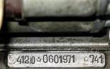
The original idle sensor has a label of the type of XX-XXXXXXX-XX. The last two digits indicate a compatibility mark:
- odd (01 and 03) interchangeable, even (02 and 04) are also interchangeable;
- between themselves these groups are not interchangeable, that is, instead of the "native" 02, the valve 01 or 03 cannot be operated.
Even in the original regulators does not prevent additionally lubricate the RCH mixture of litol and WD-40 (spring and rod). Since the replacement of the RCH is in their own hands in demand by motorists, there are counterfeit regulators that can be identified by signs:
- there are no distinctive marks on the package;
- sticker yellow color on the hull without a frame;
- the tip of the dark-colored needle;
- thin black sealing ring instead of thick red seal;
- case rivets do not have a hats with a diameter of 3 mm;
- white spring instead of a black product with frequent navive;
- the housing is shorter than 1 mm.

The correct operation of the idle sensor allows to reduce the wear of the piston group, as well as crankshaft car. In case of signs of incorrect operation of the device, the controller check can be performed manually, a multimeter or using homemade stand.
[Hide]
Purpose of idle sensor
PCX assignment in vehicles equipped with an electronic ignition system:
- The microprocessor module is the ratio of air and fuel when creating the fuel-air mixture in the injection force unit.
- The control unit refuses a certain amount of gasoline or diesel fuel.
- Electronic type of systems is equipped with crankshaft controllers, detonation and flow meter. In accordance with the readings of these devices, activation fuel pump. The ignition is distributed over specific CBO cylinders.
- If the driver goes the gas pedal, the fuel flap is completely closed. This leads to the fact that the proportions of the combustible mixture are disturbed. Combustion products move to the chamber when the pressure difference occurs between the graduation and intake manifolds.
The idling sensor in electronic ignition systems performs the function of adjusting the composition of the combustible mixture during engine starting. With the help of signals that the controller sends, the microprocessor module decides to enrich the fuel. At the same time, he ignores the readings that the throttle regulator sends. The sensor transmits signals over the line. If necessary, it opens a free channel for which air passes. This leads to an engine speed leveling while driving or idling.
User Roman Lozova presented detailed review Controller from the manufacturer General Motors for the car Daewoo Lanos.
Principle of operation
The principle of valve operation is as follows:
- The control unit is calibrated the sensor readings if it is detected in the system.
- The controller itself is a stepping electric motor. It is equipped with a conical needle, which is located in a special hole channel of the throttle node.
- The regulator does not transmit information to the microprocessor module, but it receives it from it. Therefore, it is more correct to call it not by the sensor, but the executive mechanism is the valve.
- The control unit determines the signal from the flow meter, which in the combustible mixture there is no air. Then he compares these impulses with those that transfers DPDZ.
- Voltage comes to the regulatory device. This leads to the nomination of the needle from the channel. The missing air volume is fed to the combustible mixture for mixing.
Also, the microprocessor module receives pulses about the refrigerant temperature level and motor fluid. If the engine starts at low negative temperatures, it must be warmed, which will reduce wear of elements and friction nodes. To enrich the mixture, the channel of the idle sensor is opened, for this, the driver does not need to harm for gas.
At the beginning of the device, the algorithm of action is such:
- The key is scrolled in the lock, the ignition is activated.
- The rod is extended until the stop. Thanks to this, the needle overlaps the bypass canal.
- When sprinkling the rod into the calibration hole, the control unit begins to count down the steps back.
- Voltage is served on the winding. As a result, the valve returns to the initial open state.
The number of reverse steps is configured during the firmware of the control unit, this indicator may vary depending on the device model. For example, on the Bosch ECU, it is 50 steps, and on the modules January - 120.
User Dmitry Shark told briefly about the principle of action, as well as the diagnosis of the idling controller.
Injector
At the input of the collector device in injector engines The throttle is used. It is equipped with an individual position definition controller at a specific point in time.
When the engine is launched or force aggregate stops, the following happens:
- The microprocessor module receives data on rotation revolutions.
- The control unit analyzes the operation of the power unit, clarifies the target purpose.
- Indications from the throttle and air controller are compared. The control unit determines the valve closed or not. It can also "understand", which in the cylinders of the power unit comes to the mixture - depleted or enriched.
- The opening of the Valve RXX occurs. The air flow is fed bypassing the flaps. This provides the ability to maintain revolutions at a certain level programmed in advance.
In fact, several ignition system devices are involved in this process. If the car engine stops or strokes due to problems, the operation is carried out manually. This is due to the fact that the feedback in the RHX and the diagnostic system is not.
Diesel power units are not equipped with a throttle damper, so they do not use idle sensors, they are useless.
User Alex ZW described in detail about the principle of the RXH controller in the car.
Constructive features
The valve constructively consists of:
- stepping electric motor;
- four-position rod;
- spring element;
- needles.
When RXH only appeared, they were rotary or solenoid mechanisms. Such devices had two positions - open and closed. This contributed to a decrease in the efficiency of the mode of turnover of DVS. Today, four-step sensors are used in cars, characterized by the possibility of step-by-bypass.
The idle regulator itself belongs to the category suppliesTherefore, it is considered unrepretentious. It can be restored with a malfunction, but it will change cheaper completely.
Where is the RCH?
The device must be located next to the throttle of the throttle and DPDZ. In some auto, the sensor fixation can be carried out directly on the flap housing using varnish. Sometimes the device is attached using two bolts equipped with special boarding holes. The main thing is that the range from the needle to the planting flange on the installed device was 2.3 cm.
Connection scheme
Diagram of connection of an idle controller
One harness consisting of four cables is supplied to the idle speed sensor, it comes from the microprocessor module. As a result of this connection, the diagnostics can cause certain difficulties. The car owner will not be able to simply submit voltage to the terminals of the device, since the microprocessor module does it impulse.
Signs of incorrect work of RXX
Symptoms of the regulator breakdown in the car:
- Motor car stopped keeping. When moving or standing at the traffic light, the speed of the power unit can arbitrarily increase or fall, and then return to normalized. Perhaps their freezing.
- The engine engine began to trim idle. Detonation is heard - a metal knuckle from under the hood.
- During the movement, there is no compensation for the increased load on the engine engine.
- There were difficulties in the launch of the power unit. If when started, the driver has to be additionally harvested on gas, it speaks of wear and the need to replace the idle sensor.
- Provisional turns are not either supported in the insufficient level.
- The car engine can arbitrarily stall without visible cause. This happens when driving at idle, discharge gas pedals or switching the transmission lever.
- The scrolling rate of the crankshaft can arbitrarily fall when activating energy consumers. For example, air conditioning or heating systems, glass cleaning, optics, etc.
The main breakdowns and faults RXX
Causes of problems with idling sensor:
- Cut power. This malfunction may be associated with wiring in auto, oxidation or damage to the contact elements on the block. If the connection is poor quality, then such a problem will manifest periodically. Difficulties may occur when diagnosing the device.
- Pollution of the rod, which leads to its incorrect move. This problem It is the most common and manifests itself as a result of the accumulation of mud deposits in the channels of the throttle assembly. If the flap is not cleaned for a long time, then the reason should be signed on the sensor rod.
- The failure of the electric motor. Repair such a device is unlikely to succeed, the engine is subject to replacing assembly with the regulator.
- The destruction of the sealing element as a result of wear. The problem may appear immediately after replacing the sensor if the old ring is installed instead.
- Stem wear. If the regulator is working, then the movement of the curtain should be carried out without bite, slippages are not allowed in worm gears. To determine the status of the design elements, you will have to disassemble the device.
About the reasons, as well as signs of problems in the work of the idling valve told the "SDELAJ SAM! Pljus Interesnoe! ".
Diagnostics
Before checking the operation of the controller, the following actions are performed:
- A tightening of the lever is made parking brake. Under the vehicle wheels it is necessary to put anti-collective stops.
- Opens motor compartment The car, the negative terminal is disconnected from the battery. For this, you need to weaken the tightening on the retainer.
- Examination is performed open space. It is necessary to find an idle regulator.
- From the device shut off the shoe with wire.
Manual checking
This diagnostic stage is considered the simplest in terms of implementation:
- From the device turns off the shoe with wires.
- Two bolts are twisted, the controller is retrieved.
- The sensor is connected to the microprocessor unit. The controller at the same time must be kept in hand.
- Engine starts, it is desirable to make a helper. At the moment, the rod must draw into the coil to the end. This occurs as a result of the receipt of the pulse from the control unit. Then he should navigate for a short distance.
Checking the idling knob manually allows you to determine the performance of the rod. When it is executed, you can make sure that the item is not flex and does not enhance inside the device.
But this version of the verification does not give a 100 percent result. Mounted on the car, the modification of the idling sensor does not match the firmware of the microprocessor unit. The rod is extended, but the required value for its extension is unknown. Therefore, the shoe and the plug is checked, and the marking is available only on the last one.
For visual verification It is necessary to diagnose the integrity of the electrical caps and coils. It should also be monitored by the state of the bypass channel and the needle for wear.
On the performance of the inspection manually, as well as about other methods for testing the idling valve, the user Igor Belov said in detail in detail.
Diagnosis of multimeter
You can check the operation of the controller using the tester as follows:
- From the regulator in the engine compartment, the connector with a wire is turned off. If the car is equipped with a 1.6 liter engine, then you need to unscrew the two fastenings of the throttle mechanism to the receiver. Then it moves away from the end of the latter by about 1 cm.
- First, the tester performs the diagnostics of the electrical controller, to make sure whether the voltage is received or not. The negative terminal of the multimeter is connected to the mass, that is, the body or car engine. Positive contact must be connected to the conclusions A and D, they are marked on the connector.
- Ignition activation is performed, the tester readings are read. The multimeter must be adjusted to the operating mode. The resulting voltage value should be at least 12 volts. If this parameter is below, it is likely that the problem is discharge rechargeable battery. With the complete absence of power, you need to make sure the integrity of the electrocups or the control unit.
- Ignition turns off. The next step will be diagnosed directly controller.
- The multimeter is reconfigured into the resistance measurement mode, its terminals are alternately connected to the contacts A and B, and then with C and D. The resulting diagnostic value should be about 53 ohms.
- Then the resistance is performed between pairs A and C, as well as in and D. The working value should strive for infinity. If the obtained values \u200b\u200bturned out to be different, the sensor is subject to replacement.
Impulse check on a homemade stand
You can assemble a homemade device without chips, its scheme is shown below:
- Equipment uses 6 volts charging. It can be taken from a mobile phone.
- Pads on the connectors are purchased in any thematic store.
- When diagnosing, the sensor is turned off from the microprocessor module. Stem check is performed. If the luminous indicator of the homemade stand will burn brightly, this suggests that the rod of the regulator is faulty. If the light bulb will burn half of power, then the mechanism is working.

Simple homemade stand for diagnostics
The price of such equipment is at least 1,500 rubles. Given the low cost of the idle sensor, the use of a branded stand is economically unprofitable.
How to clean the idle regulator?
Cleaning the proven RCH is considered on the example of the car Chevrolet Niva:
- Opened motor compartment and turns off the battery. To do this, disassemble the cover of the air filtering device, which is removed and removed to the side.
- A shutdown of the pad from the air controller is performed. The connector is located on a rubberized thick corrugation connecting the intake manifold device and cover air filter. This block is attached by means of a special P-shaped bracket. When dismantling, it can jump out, so you have to be attentive.
- The corrugation is then disconnected from the intake manifold, it is fixed using a clamp. The same must be done with the rubberized nozzle, it connects the corrugation with the valve cover of the power unit. The hose is fixed with an iron bracket.
- A thin nozzle connected to the intake manifold device is disconnected, it dismantled with it. This hose is tightened to the fitting.
- Inside the nozzles, you can notice contamination in the form of a car and traces of engine fluid. All hoses are cleaned and washing, after which they need to be purged. To perform the task, it is recommended to use a special cleaning agent or WD-40 liquid. The main thing is that the tube is complete with the balloon.
- The idle speed sensor itself is made in a black plastic case and is installed in intake manifold. The plug is turned off and two bolts are twisted, which fix the device. The procedure is performed using a short screwdriver with a crust tip, pre-with bolts need to remove traces of sealant. When dismantling the device, the sealing ring should also be removed.
- PCH cleaning is performed, for this you can apply fuel. The procedure is carried out using vehicle and cotton sticks. You can not pour into the mechanism a lot of fluid in order not to deduce it. After each clearing, the sensor must oxide and dry.
- It is recommended to remove the dirt from the intake manifold device, the contamination is removed using rags. It is cleaned by the selection of the idling sensor across the depth. Also remove contamination from the device fitting.
- After cleaning, the entire design is assembled in the reverse order. A new rubber ring is installed on the idle speed sensor, after which the controller is mounted in place and fixed. The connector is connected to it, the air filtering device is installed back.
Dismantled corrugation with hoses
Removing the RHX from the landing place WD-40 Liquid Sensor CleaningWhat do you need to know when replacing RXX?
To change and make the installation of a controller that allows you to adjust idle turns, you need to pay attention to the stem position. It is impossible to allow it to be strongly nominated. This may occur if before installing the device will be connected to the block and the ignition is activated. Hands to moving the rod is not allowed.
If the valve with an extended needle put and tighten the fixing screws, it may damage the device as a result of the worm transmission cutting. Repair this sensor will not work. Depending on the vehicle model, after installing a new regulator, it may be necessary to calibrate it. In some cars, this procedure is carried out using special equipment or stand.
On VAZ cars, calibration is performed as follows:
- A terminal is connected to the negative battery output.
- The key in the lock scrolls to turn on the ignition for ten seconds. You do not need to run the power unit.
- The ignition is turned off.
Ussyuk user told about self-replacement idling valve on the example of the car Lada Samara.
To increase the life of the sensor, it is necessary to follow simple rules:
- Replacing the air filtering device must be carried out on time.
- Cannot be left vehicle For a long parking lot in the winter. At low negative temperatures, the car owner should periodically launch the power unit, warmer it and produce penitz. This will develop a valve to prevent its jam.
- It is impossible to allow third-party fluids to enter the throttle zone. Sprays for quickly launch The engine usually does not represent dangers for the sensor, but they do not even overdo it.
Sensor selection nuances
The original monitoring controller has a labeling type XX-XXXXXXX-XX. The last two characters determine the compatibility mark.
Read more about them:
- odd symbols (03 and 01) are interchangeable, as well as even (04 and 02);
- these groups of devices cannot be replaced, that is, even impossible to put instead of odd.
It is possible to determine the underliest low-quality idling sensor by several features:
- there are no distinctive marks on the device packaging;
- the string tip has a dark shade;
- yellow sticker on the case of the device has no framework;
- original sensors are equipped with a thin black seal, and fakes - a thick red ring;
- the housing of the poor-quality device will be shorter than 1 cm;
- neoriginal sensors are equipped with a white spring instead of black, its coils are more rare;
- there are no caps with a diameter of 3 mm on rivets.
How much does idle regulator cost?
The cost of the new valve depends on the manufacturer, as well as the brand of vehicle.
Video "Independent calibration and removal of a rod with RXH"
User Ruslan K told how at home to make a dismantling of the needle from the regulator and perform its calibration without special equipment.