How to make electronic ignition on UAZ. Contactless ignition system
Any car is possible due to the ignition of the combustible mixture in the cylinders power aggregate. To ensure the normal efficiency of the motor, the correct setting (SZ) is required. In addition, all the elements, including the coil, the car of the UAZ car and other components should always be in working condition.
[Hide]
Description SZ on UAZ
How is the installation, adjustment and adjustment of the ignition circuit on AUZ 417 or any other? We will tell about this below. But for starters, let's figure it out in principle the work of the node, as well as the varieties of SZ.
Principle of operation of SZ.
SCH Scheme and the designation of its elements for old UAZ enginesAs already said, ignition on UAZ performs one of the main functions when the power unit is launched. Thanks to this system, the procedure for igniting the fuel-air mixture in the cylinders of the power unit by filing a spark is carried out. The spark is directly filed on, each of the cylinders is installed on the same candle. All of these NWs function in order mode, flamming a combustible mixture at the required period of time. It is also necessary to take into account that the ignition system on vehicles provides not only to supply the spark, but also determines its strength.
The battery of the transport is not able to generate the voltage and the current necessary for the ignition of the mixture, since this device produces a current of only a certain force. Opens the ignition system, the purpose of which is to increase the power of the machine battery. As a result of the use of SZ AKB allows you to transfer sufficient voltage to the candle to ignite the mixture.
Types of ignition systems
 Contactless scheme SZ with switcher for UAZ
 Today, three main types of ignition systems are distinguished, which can be installed on a car:
- Contact SZ. It is considered morally obsolete, but continues to be successfully used on vehicles of domestic production. The principle of operation is that the system issues the necessary impulse, which appears due to the operation of the distribution component. The device itself is simple, and this is a plus, because in case of breakdown, the driver will always be able to diagnose and repair independently. The cost of replaceable components is not high. The main components of the contact type system are the battery, shortcut, drive, candles, capacitor, as well as a breaker with a distributor.
- A system called transistor. This type is equipped with many transports. If compared with the above view, the system is characterized by a number of advantages. First, the spark produced has a greater power due to increased level Voltages in the secondary winding of the ignition coil. Secondly, the contactless system is equipped with an electromagnetic device, allowing to provide stable work, as well as the transfer of energy to all nodes. As a result, when proper setting DVS, this allows not only to increase the capacity of work, but also save fuel. Thirdly, this is convenience in terms of service node. To ensure performance for a long time, after setting up and installing a traver drive, this element needs to be lubricated from time to time. To ensure normal performance, the element is lubricated every ten thousand mileage kilometers. As for the shortcomings, this is the complexity of the repair. Repair the device itself is unreal, this requires a special diagnostic equipmentwhich is only a hundred.
- Another option SZ - electronic, Which today is most technological and expensive, so new transports are equipped with them. Unlike the two systems described above, the electronic ignition system is characterized by a complex device, which ensures the performance of not only the moment, but also other parameters. Currently, electronic systems are equipped with all modern cars. The key advantage is a more simplified procedure for adjusting the angle of ahead, as well as the absence of the need to periodically check the contacts for oxidation. In practice, the fuel-air mixture in the electronic ZZ engines is almost always burning in full.
This type also has its own minuses, in particular, on the issue of repair. It is unrealistic to produce it with your own hands, since equipment needs for this. detailed instructions On the adjustment of the ignition using the light bulb is presented in the video below.
How to put it?
How after connection, the ignition installation is made for proper operation of the motor?
What is the order of how to properly set the node setting, read below:
- To begin with, transport must be fixed on the spot, turn on hand brake. The piston of the first cylinder must be set to the upper dead point, consider the hole on the pulley crankshaft Must match the label, which is located on the distribution gear cap.
- From the switchgear you need to dismantle the lid. Having done this, you will see the slider that is against input 1, inside the lid. If it is not, then the crankshaft must be rotated 180 degrees and put the octane-corrector for 0. Using a wrench, tighten the pointer to the dispenser's controller housing so that it is combined with the average label at the octane corrector. Screw fixation plastic to the camshaft housing a little release.
- Carefully turn the housing, holding the runner with your finger so that it does not rotate. So can eliminate the gaps in the drive. The body turns to the moment until the sharp part of the petal on the stator is aligned with the red risk on the rotor. Plate Fix the screw to the controller body.
- The next step is to install the controller cover in place and diagnostics. They must be installed in accordance with the procedure for the functioning of cylinders, that is, the first, second, fourth, third. When the moment of ignition is installed, it is necessary to diagnose the correctness during the ride.
- Run the power unit and warm it about ten minutes until the temperature is about 80 degrees. Moving on a flat and straight road with a speed of about 40 km / h, sharply press the gas pedal. If with a speed set of up to 60 km / hour you will feel or hear detonation, it should be short-lived, then everything is done correctly. If the detonation is very strong, the distribution controller must be rotated on half or one division counterclockwise. With the absence of detonation, the established advance angle must be increased, that is, the controller should be rotated clockwise.
Classic of domestic auto industry
Many UAZ cars are equipped with a contactless ignition system. It makes it possible to save fuel, reduces the number harmful substances In the gases, it makes much easier to launch the car in the winter.
The scheme for connecting the electronic ignition on the UAZ is not so complicated as it may seem at first glance. A person who is at least a bit disassembled in the technique will be able to repair and correct malfunctions if such arose.
Ignition system for UAZ 469
The ignition system on UAZ 469 can be made not only in a hundred, but also with their own hands. It consists of:
- ignition coils or traver;
- switch;
- emergency vibrator;
- variator (added resistor);
- spark plugs.
Today, it is most often preferred by contactless ignition systems.The most interesting in them is the switch.
If the crankshaft rotates with a frequency of 500 revolutions per minute, then it turns out that the signal will change too quickly at the output of the sensor. This mode is used if you start the engine starter. At this time, there will be no one spark on the candlelight, but a lot that will make it easy and quickly start the car. Ignition on UAZ have a simple design.
Contactless ignition is more convenient to use than contact.
Installation Instructions
Set contactless ignition On UAZ 469 is quite simple. It is easy to configure and install it, and the reliability of ignition UAZ can only please. It works very precisely, even in the cold season, when the car is quite difficult to start.
After new system It was bought, it must be installed. To install, you will need:
- drill;
- self-tapping screw;
- drill;
- key to 38;
- key horny at 13;
- keys of precipitated and end 10 and 8.

Node on the car
Ignition on UAZ 469 is as follows:
- First, the engine must be installed on the TWM Tag using 38 keys. Before doing something with the technique, you need to remember the location of the details before replacement.
- We look at how the runner and the distributor is installed to install a new one in the same position. Next, we find a place where the ignition coil is located on which we find a B + label and watch the location of the wires and what is attached to. After everyone looked, you can unscrew the coil. We remove the distribution lock, place the switch, and also set the ignition coil and secure it to the body. Connect standard wires. From the wire switch with a label + attached to the terminal b, and the second wiring is mounted to the terminal.
- Connect the distributor, but the nut is not delayed completely. It is necessary to connect the wires from the switch to it. After that, you need to check the location of the runner and the distributor, put on the lid and connect all the wires in the order in which they were before replacement.
- When everything is already replaced and fixed, the engine should be launched, check how it works, and adjust inaccuracies.
Adjusting the ignition UAZ is a fairly simple occupation. On the engine in working condition, it is very slow to twist the distributor to find the position in which the engine will work smoothly, and the turns will be high.
The UAZ 469 car has a ignition coil, which is simultaneously a kind of transformer converting a low voltage to high. When the engine is running, the current passes through the added resistor into the primary winding of the ignition coil. It is located between the legs of the fixing brackets in the insulator.
When the engine starts using a starter, the resistor turns off, and the current enters the primary winding, without falling into it, which greatly facilitates the start of the engine due to the amplified spark.
Device coil

Underwater ignition on the jeep
UAZ 469 ignition coil has a complex design:
- the withdrawal of the high voltage is screwed;
- voltage output;
- cap;
- spring contact;
- low voltage clamp;
- gasket for sealing;
- crepe bracket;
- magnetic pipelines;
- contact plate;
- primary and secondary winding;
- laying for isolation;
- housing;
- insulator;
- iron core;
- mass isolation;
- resistor Additional and its insulator;
- screw and plate for mounting the resistor.
The rubber performs the function of the distribution and interrupt of the ignition of UAZ 469. It has a vacuum and centrifugal regulators. Centrifugal changes the angle of ignition UAZ depending on which frequency crankshaft Or distribution roller rotates.
BSZ spark plugs are a very important element.With their help in the combustion chamber in the cylinders, the working mixture is flammed and gives a good spark so that the car quickly started. Most often, the A12BS candles are used, which cannot be disassembled, so in the event of a malfunction you need to have new, which can be quickly and easily replaced.
Wires for high voltage are made of PVL-1 wire. They combine the coil with the distributor, and the distributor with candles. Candles are attached to the central electrode using special tips with resistors.
UAZ Car Ignition System
Device
The ignition system circuit is shown in Fig. 2. The ignition system includes: accumulator battery, generator, ignition coil, ignition distributor, ignition candles, wires and ignition switch.

Fig. 1. Enable an additional starter relay scheme for checking and adjusting: 1 - rechargeable battery; 2 - Reostat; 3 - warning lamp; 4 - relays; 5 volt meter; 6 - Switch

Fig. 2. Ignition system scheme: 1 - rechargeable battery; 2 - relay regulator; 3 - generator; 4 - Ignition Candle; 5 - distributor; 6 - ignition coil; 7 - ignition switch and starter; 8 - ammeter; 9 - starter; 10 - additional starter relay; 11 - Mass Switch

Fig. 3. Ignition Coil: 1 - High Voltage Screw; 2 - cover; 3 - high voltage terminal; 4 - Contact Spring; 5. - Low voltage terminal; 6 - Celebration gasket; 7 - metal plates for increasing the magnetic flux; 8 - fastening bracket; 9 - contact plate; 10 - primary winding; 11 - secondary winding; 12 - body; 13 - insulating gaskets; 14 - insulator; 15 - iron core; 16 - insulating mass; 17 - resistance isolator; 18 - additional resistance; 19 - plane fastening additional resistance; 20 - screw fastening resistance

Fig. 4. Ignition distributor: 1 - Low Voltage Terminal; 2 - condenser; 3 - Filter brush; 4 - Vacuum regulator traction; 5 - vacuum regulator; "--diaphragm; 7, 17 and 25 - springs; 8 - Bearing; 9 - roller; 10 - body; 11 - ball bearing; 12 - fixed panel of the interrupter; 13 - mobile panel; 14 - spring cover holder; / 5 shn; 16 - high voltage terminal; 18 - central contact with suppressive resistance; 19 - rotor; 20 - tok offshore plate; 21 - cam; 22-plastic cam; 23 - Pottle weights; 24 - Georgics of the centrifugal regulator; 26-bills of roller; 27 and 28 plates of the Octane Corrector; 29 - nuts; 30 - locking screw; 31 - Breakfast Spring; 32 - Plate with fixed contact; 33 - contacts; 34 - armored lever; 35 - Adjusting Eccentric
The ignition coil B7-A is a transformer that converts low voltage of the primary chain into high voltage of the secondary chain required to obtain a spark between the electrodes of the candles and the ignition of the working mixture in the engine cylinders.
Attaching the ignition coil into the electrical equipment chain is shown in Fig. 2. In the primary winding of the coil, the current passes through the added resistance, which when starting the engine, the starter turns off automatically, and the current enters the primary winding, bypassing it, which is reached the amplification of the spark and facilitating the engine start.

Fig. 5. The operation of the centrifugal regulator of the ignition timing: A - on idling engine; b - at the maximum number of engine crankshaft; 1 - cam; 2 - Georgic; 3 - fist plate; 4 - roller; 5 - Pottle of Georgic, 6 - Spring
The ignition distributor of the RZ-B is mounted on the left side of the cylinder block and drives against the oil pump roller.
The ignition distributor is designed to interrupt the low voltage current in the ignition coil circuit, the high voltage current pulse distribution of the engine cylinder cylinder candles of the mixture of the mixture, depending on the number of revolutions and the engine load.
The dispenser interrupter consists of a fixed contact plate, a rolling pin lever and a four-gamped cam, which, rotating, blurs the contacts, racing the arms on the lever pad. The gap between the interrupter contacts is regulated by an eccentric. In parallel, the contacts include a CN-4 capacitor with a capacity of 0.17-0.25 microf.
The high voltage current distributor consists of a rotor and covers with electrodes that are connected by wires with a coil and candles. The rotor of the distributor during rotation transmits high voltage current pulses from the secondary winding of the ignition coil to the candles in accordance with. Procedure for the work of cylinders.
The distributor has a centrifugal and vacuum regulators that automatically change the ignition advance an octane-correlator to manually adjust the ignition angle depending on the octane number of gasoline used.
The centrifugal controller changes the ignition angle depending on the rotor of the engine (or the distributor roller).
The vacuum controller changes the ignition angle depending on the engine load (the vacuum in the inlet tube).

Fig. 6. The work of the vacuum regulator of the ignition advance: A - the discharge in the carburetor is small; b - discharge in the carburetor Veliko: 1 - tube fitting from the carburetor; 2 - adjusting washer; 3 -prot; 4 - lid vacuum regulator; 5 -Diaphragma; 6 - the case of the vacuum regulator; 7 - screw fastening of the regulator; S - thrust; 9 - pin; 10 - mobile panel of the interrupter; 11 - Contacts; 12 - arm arm; 13- File
The octane corrector provides a change in the ignition angle within + 10 ° at the corner of the rotation of the crankshaft.
The Ignition Candles A14U of an unbearable design have the length of the whip of the housing 14 + 0.5 mm and the metric thread M14x1.25. Clearance between candle electrodes 0.8-0.95 mm.
When adjusting the gap between the electrodes of the candles, it is necessary to bend only by the side electrode, since the insulator of the candle is bursting to the central electrode.
The ignition switch and starter of the VK21-K (Fig. 150) is used to turn the current in the primary chain of the ignition system and to turn on the starter and the radio. Installed switch on the instrument panel.
On the plastic base of the lock switch, the AM (ammeter) terminals are placed, KZ (ignition coil), st (starter), etc. (receiver). The AM terminal is under constant voltage.
When the key turns into the first right position of the AM terminal connects to the KZ terminals, etc., ignition circuit control devices, wiper, radio receiver, windshield blowing fan, cockpit and body heating fans. The radio receiver is only installed on the UAZ -452B bus.
When the key turns into the right extreme position, the AM terminal is connected to the KZ terminals and the ignition and the starter are turned on.

Fig. 7. Ignition Candle with Poverty Resistance:
1 - the body of the stubborn resistance; 2- contact; 3-Contact Spring; 4 - resistance; 5 - central electrode; 6 - retaining spring; 7 - insulator; 8 - seal; 9 - Candle hull; 10 - gasket; 11 - side electrode

Fig. 8. ignition switch and starter: 1 - insulator with contacts; 2 - contacts; 3 - movable contact plate; 4 - Clems of AM-, 5-terminal KZ; 6 - terminal PR; 7 - Spring of the contact plate; 8 - rotor; 9 - Rotor Spring; 10 - body; 11 - locking cylinder; 12 - shut-off larvae; 13 - stop ring; 14 - key; 15 - spring; 16 - fixture balls; 17 - Nut Mounting Castle to Panel
When you turn the key to the left of the AM terminal connects to the terminal PR - the radio is turned on.
Maintenance
At T-1 it is necessary:
- Check reliability electrical connections and fastening the ignition system devices;
- Lubricate the distributor roller by turning the cap of the cap oil. Throw one drop of oil used for the engine, on the axis of the interrupter lever, 1-2 drops on the cam flushing and 3-4 drops into the cam sleeve (after removing the rotor and filter under it). When lubricating the cam and the axis of the interrupter, it is necessary to ensure that the oil does not fall on the contacts of the interrupter.
At TU-2, in addition to the works provided for by that-1, perform the following works.
Check the condition of low and high voltage wiring and clean them from dust and dirt.
Finding the spark plugs, clean them from the car and adjust the gaps between the electrodes.
Inspect the contacts of the distributor, remove the dirt and oil from the contacts, wiping them with suede, slightly moistened in gasoline. Then wipe them with a clean dry suede or a tissue that does not leaving the fibers on the contacts.
The burnt or oxidized contacts should be carefully cleaned with a special abrasive plate included in the driver's tool kit, or a shallow glass skurt.
After stripping contacts, it is necessary to wipe the suede, slightly moistened in gasoline, and establish a normal gap between them.
Check the dipped gap between the interrupter contacts and, if it is more than 0.05 mm differ from the nominal (0.35 - 0.45 mm), adjust it.
To adjust the gap, it is necessary to turn the crankshaft of the engine with the handle so that the interrupter's cam fully open contacts. Then weaken the screw that fastening the fixed contact plate and, rotating the screwdriver head of the adjustment eccentric, shift the plate, and with it, and a fixed contact in the desired direction before getting the desired gap. After that, tighten the screw and check the gap to the dipstick again.

Fig. 9. Checking the interrupter spring tension
Check the lack of hot lever on the axis, for what to squeeze the lever with your finger and release it. The lever released must quickly return (under the action of the springs) and contacts must be closed with a click.
If the closure did not happen or the sluggish contact of the contacts occurred, it is necessary to eliminate the jealous and adjust the tension of the interrupter's spring within 500-700 g, removing the lever and bending the spring in one direction or another, as needed. Spring Tension The interrupter lever is checked using a spring dynamometer, as shown in Fig. nine.
Once a year, but no less often than in 25,000-300,000 miles of running and, if necessary, repair the distributor in the workshop. In this case, the distributor is disassembled, inspect all the details and, if necessary, replace.
When the dispenser is bulkhead, lubricate all the rubber parts, and the cam filhes are impregnated into the oil and pressed.
Remove the fixed panel of the breaker, wash the ball bearing and lay a new one in it. consystem lubricant LZ-158 or cyatim -201. Before panel formation, the ease of rotation of the ball bearing is checked and, if necessary, additionally turn its outer ring to the elimination of the healing.
Check the amount of carbon resistance; It must be within 6000-15 000 Ohm.
After 40,000-50,000 km of the car run in the case of a large radial backlash of the distributor roller, causing violation of spar formation, replace the roller bearings of the distributor.
The main malfunctions of the ignition system and how to eliminate them
The frequently encountered dispensers include: violation of the normal gap between the interrupter contacts, the oxidation of the contacts, the wear of the textolite protrusion lever of the interrupter, the capacitor insulation breakdown, the disorder of the insulation of the cover and rotor of the distributor, decrease the elasticity of the springs of centrifugal or vacuum control regulators, the discharge of the vacuum regulator.
Violation of a normal gap between contacts, as well as their oxidation causes interruptions in the engine operation.
To troubleshoot a malfunction, it is necessary to clean the contact of the interrupter, and then adjust the gap between them, as described above.
Wear a textolite protrusion lever of the interrupter leads to the fact that it becomes impossible to increase the gap between the contacts to normal (0.35 - 0.45 mm) of the magnitude. The lever with a worn protrusion is replaced.
When testing the capacitor isolation, the engine begins to work with interruptions, and then stops. The contacts of the interrupter are greatly overtaken. Faulty condenser replace new.
Violation of the insulation of the cover and rotor of the distributor entails the appearance of interruptions in the engine operation. Faulty lid and rotor are replaced.
A decrease in the elasticity of the centrifugal regulator springs is accompanied by the appearance of strong detonation knobs when moving the car (not only during acceleration, but also when moving at an average rate). In this case, it is necessary to increase the tension of the springs by sweeping their racks, after which check the distributor on the SPZ -6 booth.
A decrease in the elasticity of the spring regulator springs causes a change in an increase in the angle of a ignition advance at medium and large engine loads, which is accompanied by the appearance of detonation stuffs. In suspected of a decrease in the elasticity of the spring of the vacuum regulator, the distributor must be checked on the SPZ -6 stand. To increase the elasticity of the spring, install an extra washer between the spring and the fitting. After that, the vacuum regulator again check on the stand.
The violation of the tightness of the vacuum regulator usually occurs due to damage to its diaphragm. In this case, the regulator ceases to increase the ignition advance on small and medium loads, as a result of which the fuel efficiency of the car is worse. The tightness of the vacuum regulator is checked on the SPZ -6 stand. In the absence of a stand, the tightness of the vacuum regulator can be checked as follows. Remove the regulator from the distributor to bring air under the pressure of 3-4 kg / cm2 and immerse in water. At the same time, air bubbles should not be released at the site of the hull and nut connections and at the location of the lever.
The ignition coil malfunction includes insulation tributes and intersensional closures of primary and secondary windings, cracks in the lid, as well as the abnormal resistance. With breakdowns of the insulation windings, the engine stops working and it fails to start. With inter-touch closures, interruptions occur in the engine. When an additional resistance is blocked, the engine is easy to start starter, but the starter turns off the starter immediately.
Dropped additional resistance must be replaced. Faulty ignition coil replace new.
Faults of spark plugs. Any of faults of spark plugs (violation of a normal gap between the electrodes, the deposition of a large nagar layer on the housing and insulator, the appearance of cracks on the insulator) entails the occurrence of interruptions in the engine operation. The non-working candle is detected by alternately disconnecting each candle (by removing the carbetic tip) when the engine of the crankshaft operating on the lowest possible turnover of the engine. Disabling the faulty candle will not affect the uniformity of the engine. When disconnecting a good candle, the uneven operation of the engine will increase.
The faulty candle must be turned out, clean and check on the Garo model 514.
Instead of a faulty candle, you need to screw the new, checking the pre-gap between its electrodes. When installing a candle in place under its body, a copper gasket must be installed.
The gap between the electrodes of the candle is checked by round affairs available in the driver's instrument. At the same time, it is impossible to pylize with a flat probe, since it is not "" in the deepening of the sideline, the candles sampled on the process of its work.
The ignition switch is very durable and, as a rule, works without repair or replacement for several years.
Installation of ignition
Ignition of the engine must be installed with great accuracy, since even with small errors in the installation increases sharply, the fuel consumption increases, and the engine power decreases.
The order of operations when installing the ignition is next.
Remove the distributor cover and rotor and check the gap value between the interrupter contacts. If necessary, adjust the gap. Put the rotor in place.
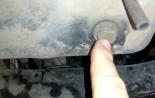
Remove the first cylinder candle and closing the first cylinder candle with a finger, turn the engine shaft by the starting handle before the start of the outlet of the air from under the fingertip it will occur at the beginning of the compression stroke in the first cylinder.
After making sure that the compression began, carefully turn the engine shaft before the coincidence of the hole on the pulley with the pin.
Smooth setup nuts Set the Octane-corrector scale to zero division.
Loosen the screw fastening of the interrupter housing and rotate the dispenser body counterclockwise so much so that the interrupter's contacts are closed.
Take a portable lamp and using additional wires to connect one of the wires to the mass, the other to the low voltage terminal on the coil (which is attached to the wire that goes to the distributor).
Turn on the ignition and rotate the dispenser case clockwise until the light bulb flashes. Stop rotation of the distributor should be exactly at the time of flashing the light bulb. If it failed, repeat operation.
Secure the casing of the distributor with a screw, put the lid and the central wire in place.
Check the correctness of the connections of wires from the candles, starting from the first cylinder. Wires must be attached in order 1, 2, 4, 3, counting counterclockwise.

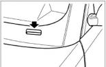
RIC. 10. Definition top dead Points
After each ignition installation and after adjusting the gap in the interrupter, you need to check the accuracy of setting the moment of the ignition of the combustible mixture, listening to the engine operation when the car is moving. Refiguring the ignition installation can be made by Octane-corrector, without weakening the fastening screw. To do this, it is enough to rotate the smooth setup nuts, unscrewing one and shrinking the other.
Moving the arrow to one division of the Octane-corrector scale corresponds to a change in the ignition installation by 2 °, counting on the crankshaft. When turning the dispenser's housing counterclockwise, the ignition installation will be later clockwise - earlier.
The most advantageous ignition advance will be this, in which during a sharp overclocking (full opening of the throttle) of a fully loaded car on a horizontal road with an initial speed of 30-35 km / h in direct transmission will hardly listen to the unit detonation stuffs in the engine cylinders. If there are no intense drive of the car the car, it means that ignition later; On the contrary, the appearance of a number of consecutive distinct knocks indicates too early ignition.
TO Atientary: - UAZ
Step 1. Preparation
General view of ATE2 set:
It is still necessary, in addition to the system itself, a set of a chauffery tool. At a minimum, you need: horn keys on 8, 10, cross screwdriver and "curve" starter (if a body elevator is made or not the ability to use the "curve" starter - you need something that you can turn the engine).
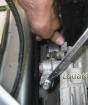
Step 2. Dismantling of the native distributor sensor (hereinafter - the traver) and the ignition coil
Before removing the native rubber, you must turn the engine to combine the tag on the "5o to NTC of the 1st Cylinder" with the pin on the block. Rotate the engine clockwise, we combine the labels and then remove the lid of the traver. If the slider is directed towards the cylinder block, then you can dismantle the native rubber. If not, the slider is directed to the opposite side of the block, you need to turn the engine for another turn. Now the slider looks at the engine.
To dismantle the rubber, remove the high-voltage wires and the hose of the vacuum controller and the key to 10 turn the fastening bolt of the octane-corrector plate to the drive housing and, shaking the rubber, take it out. In the event that there are not enough forms of hands, we get a slotted screwdriver from the bottom of the octane-corrector plate, and, leaning on the drive, shifting the rubber upward.
Then remove the regular ignition coil. We unscrew 2 nuts and remove the wires from the conclusions. The coil itself is screwed with 2 screws to the engine shield.
Step 3. Installing a new trambling and ignition coil.
Before installing a new rubber, you need to mount the octane-corrector plate on it. This plate has no fixed position on the housing of the traver. The location of the primary installation is a little left of the housing of the vacuum regulator, if you look at the rubber on top. Putting the plate on the housing, and putting it up with an approximate location, 10 tighten the nut on it. Thus, the plate crimps the housing as a clamp.
ATTENTION (!) - Do not make an excessive effort, this material is very fragile!
Finally, the position of the plate is selected already during the exhibition of the engine on the engine.
Now the rubber is ready to install on the engine. Whatever the rubber rose into the drive, it is necessary to achieve the coincidence of the protrusions on the coupling from the bottom of the traver with the slots on the drive roller. Position the rubber next to the drive and turning the coupling with a hand, achieve an exemplary protrusion with a slot on the roller.
ATTENTION (!) - The protrusions on the coupling coincide with the slot only in the same position, because The protrusions are shifted from the center line.
We insert the rubber into the drive and, turning it out of the side, to the side of the coincidence of the coupling with the drive roller. On the installed rubber, there should be no gap between the octane-corrector plate and the drive hull itself.
Remove the lid of the new traver. To do this, unscrew the crossed screwdriver 2 screws. The slider should look at the motor shield.

The fact is that at the ATE-2 traver, the numbering of the 1st cylinder does not coincide with the numbering of the standard traver. The conclusion of the 1st cylinder at the new traver is above the roof of the Hall sensor (on the cover there is a number "1" - this means a 1st cylinder). This is explained by the fact that the coupling of the ATE-2 traver is deployed to 180 °.
Then, turning the housing of the traver, we seek that the 1st cylinder connector on the lid coincided with the Runner's contact. In other words, the moment is igniting the mixture in the first cylinder. It will be the initial Woz. Naturally, it is impossible to ride it, but it is already possible to start the engine for adjustment. From the hands we wrap the fastening bolt of the octane-corrector plate to the drive housing.
Now install a new ignition coil. Put on a regular place without alterations.
Step 4. Connecting wiring and installing a switch
There is nothing complicated. If a set from the VAZ-21074 is used, then no blocks will be 3 contacts. Because In different schemes, these wires of different color, I will write their number. I think from left to right through the number of switch contact numbers (the location of the switch as on the 1st photo).
The wire from contact number 3 (colors is more often blue or blue with a red stripe) connects to the plus connector of the ignition coil. On the coil, this jack is more often indicated by the "+" or "b" sign, or "wat". To the same connector you need to connect the "+" from the regular coil.
Wire from contact number 5 (more often brown or black, this is the shortest "tail") connects to any "mass"
The wire from the last contact number 6 (more often brown with red or brown with blue) connects to the second connector on the ignition coil. It can be indicated as "K", "VK" or "RUP". On the same coil connector, the wire is connected from the EPHH control unit (if any).
2 The connecting pads are connected to the switch and the output of the Hall sensor on the rubble.
Insert the wires to the rubber. Connection order 1-2-4-3, ranging from the output of the 1st cylinder. It should work like this:

It remains to find the place to the switch, because the length of the wires does not allow it to put it on a regular place. If the machine does not participate in competitions, you can put the switch next to the fuse block. Quite a reliable and affordable place. I put the wires and secured the switch under the instrument panel in the legs of the front passenger.

It is also worth noting that not all digital tachometers that worked with a regular transistor-switter scheme can work with the hall sensor.
It remains only to adjust the uz and tighten the fastening bolt of the octane-corrector plate.
ATTACHMENT. Ignition scheme VAZ-21089

25 - ignition coil
23 - EPHH control unit
27 - Switch
The ignition procedure on the UAZ depends on the scheme that has distinctive features For each type of ignition system.
How to set ignition
In order to properly adjust and set ignition on the UAZ, it is necessary to follow the sequence of actions, which is provided in the repair manual.
Before you start adjusting the ignition system, you must install vehicle on the watching pit or a special platform for repair work and turn on the handbrake. Vehicle wheel mechanisms must be fixed by a stopper or focus. The power unit must be disconnected.

After that, you can proceed to the ignition installation. To do this, it is necessary to fix the piston of the first cylindrical element in the position of the highest dead point. At the same time, it is necessary to check that the hole on the crankshaft pulley coincides with the pin on the cover of the camshaft gear. It is necessary to slightly lower the mounting bolt, located on the plate, to the housing of the distribution equipment sensor.
Then you should remove the cover from the distribution device and turn the crankshaft by 180 °. Octane-corrector must be in a zero position. Then it is necessary to tighten the pointer to the housing of the distribution mechanism sensor so that its position coincides with the ricke of the Octane-corrector.

After that, we configure the slider, rotating it counterclockwise. This will help eliminate the gaps in the drive. When the point in the stator coincides with the label of red, you can fix the plate with a bolt.
Then you need to install the switchgear sensor cover and check the correctness of the installation of the ignition lines according to the procedure for the operation of cylindrical mechanisms (1-2-4-3). It is necessary to count in the direction counterclockwise. The ignition setting on the UAZ is completed.
If, with an increase in speed up to 50-60 km / h, the driver will feel short-term detonation, which means that the procedure was performed correctly.
In the event that there is no detonation, you need to increase the advance angle, taking the sensor clockwise.
How to check the ignition coil
Check is required in the following cases:
- The mechanism does not stall when the ignition is turned off.
- There was a short circuit.
- Candles of ignition systems came out.
- The coil is heated, which is why the system is overloaded.

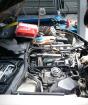
In order to check the ignition coil, you need to turn off the power unit and open the hood. Then you need to find the coil. It is recommended to follow the wires that lead from the distribution mechanism in the opposite direction. After that you need to disconnect 1 high-voltage wire From the spark plug. Before the procedure you need to wait until the engine is completely cooled. This may require 15-25 minutes.
Then you should dismantle the candle with a special nozzle. It must be done carefully and ensure that the garbage does not get into the hole, because This will cause a malfunction of the power unit. You need to connect the wire back to the candle. To perform this operation, it is recommended to use pliers with insulated handles.
After that, you need to touch the threaded side of the candle to bare metal. With the ignition on, all the elements of the electrical equipment of the vehicle will start working, it means that the coil is functioning properly. Driver performing repair workmust see a spark of blue. If it is not, it means that the system is faulty. If the spark of orange color occurs, it means that there is an insufficient amount of voltage. The reason for this can be bad contact, weak current or defects of the coil housing.

Another way to check the ignition coil connection:
- Remove the coil from the car. To do this, you need to disconnect the wires of distribution equipment, remove the fasteners from the coil body using the wrench.
- Determine the state of the mechanism using an ohmmeter. You need to touch the primary winding to the primary winding, touching 2 contacts at the same time. After that, you need to measure the state of the secondary winding and compare the obtained indicators with the factory that is in the repair manual.
Before starting work, it is necessary to establish transport to a flat surface and fix it with special locking devices. While checking the device, it is recommended to wear protective clothing (mask and glasses, as well as gloves).
How to connect ignition lock
Replacing the ignition lock involves disassembling the old and installing a new mechanism with its subsequent connection. To remove the old castle, you will need a cross and flat screwdriver.

Procedure for dismantling the old castle of the transportation system:
- Remove the fasteners from the bottom facing panel of the steering column.
- Insert the key into the lock and set it to the zero position at which the steering mechanism will be blocked.
- Remove the steering column.
- Unscrew the fastening bolts of the ignition lock.
- Insert a flat screwdriver into a small technological hole and click on the retainer that holds the lock.
- Push the castle from the landing place.
- Disconnect all wires of the system.
- Install a new lock, connect the wires and collect the mechanism by performing all actions in the reverse order.
All wires are connected in the direction of the clockwise direction.
To the output number 50 you need to connect the wire of the red color, which is responsible for the stable operation of the starter device.
To the output number 15 you need to connect the wire of blue color With a black stripe, which is responsible for heating the vehicle salon.
To the output number 30 pink wire is connected, and to 30/1 - brown.
The INT connector must be connected to a black wire that is responsible for the work. overall lights and headlights.
After all the wires are connected, you need to connect the battery terminal. To the top of the terminal, the black wire must be connected. Then you need to start the engine and check the health and efficiency of the entire ignition system. First it is recommended to check the work electrical devicesand then the serviceability of the starter mechanism.

If all the wires are connected correctly, then with a zero position of the ignition system, all elements of electrical equipment will be disconnected. When you turn the key to the first position, the operation of the system that controls the engine is activated internal combustion, generator installation, headlights and locking signals, as well as washers and glasses cleaners. When moving the key to the second position, the starter works, the rod anti-theft system Exposed and removed when changing the position of the key.
If this did not happen, it means that the wires are connected incorrectly. It is necessary to disassemble the mechanism and repeat the connection procedure.
Ignition scheme
The scheme depends on the type of IAS-3151 ignition system. In order to correctly set the contact, contactless, electronic or underwater ignition with your own hands, you need to use the repair instructions.
Contact
Connection diagram of the contact system includes such elements as:
- Lock. It is located on the steering column housing and is necessary to control the current flow between the battery of the transport and ignition.
- Battery. At the moment when the engine is disabled, the power supply of the entire electrical equipment is the battery. It complements the level of electricity, which is generated by a generator set, if it issues the voltage below 12 V.
- Switchgear. It sends a high voltage current from the coil through the distribution mechanism handle in turn to each of the system's candles.
- Capacitor. It is located on the camshaft housing and warns the appearance of a spark between open contacts of the system, protecting them from burning.
- Spark plug. The current of high voltage moves along the central electrode of these mechanisms. Between the central and side electrode, a spark appears between the central and side electrode, which sets on fuel fluid in the cylindrical device.
- Drive unit. The distribution mechanism is equipped with a direct type of drive from distribution Vala.. The speed of rotation of such equipment is 50% of the rotational speed of the crankshaft.
- Centrifugal regulator. It is necessary to install the desired angle of fooling, depending on the rotor of the motor. This mechanism includes cargoes that rotate, affect the plate with the interrupter contacts.
- Coil. Its design includes 2 isolated winding wires that are wound on the core made of soft steel. The process of compressing magnetic fields around the primary winding forms a high voltage current in the secondary winding passing through the distributor to the Ignition System Candles.

When the driver turns the ignition key, the low voltage current of the battery goes to the primary winding of the coil. After that, he begins to form a magnetic field. Due to the rotation of the power unit from the starter, the contacts of the cam interrupted device are opened. At this moment, the magnetic field begins to disappear, and the power lines and windings turns form a high voltage current. The pulse appeared turns onto the cover of the distributor housing, and the spark charge flames the fuel and air mixture in the cylindrical device of the motor.
Contactless
In order to establish the moment of contactless ignition on the UAZ, it is necessary to prepare the following tools:
- wrench kit;
- crosshead screwdriver;
- stroboscope;
- protective clothing in the form of glasses and masks;
- retaining mechanisms for wheels.
Before you begin to connect, you need to wear protective clothing and install the vehicle on a flat surface and fix its wheels using special stoppers.

First you need to put risk on the lid of the valves and combine all tags. After that, turn out the candle of the first cylindrical engine mechanism and remove the cover from the main distributor. If you pull out the first cylinder candle, you can track the stroke of the piston part of the motor.
Then it is necessary to insert a long screwdriver into the cuplee well and turn the crankshaft for the ratchet clockwise by setting it to the position of the highest dead point. This will help push the screwdriver back from the well. The label on the pulley should be put up opposite the long risks on the case of the power unit.
After that, you need to weaken the contact nut, which presses the rubler to the cylinder block. Rotating the housing, it is necessary to install one of the slots in the gap of the Hall sensor. At this time, the contact of the movable type of the runner must fully coincide with the side contact at number 1 on the lid of the traver, the body of which must be turned into a steady position and fix with the help of a mounting nut.
Then you should tighten the fastening nut and install the lid with the candles in place.
When all the work is completed, you need to start the engine, warm it up to a temperature of + 50 ... + 60 ° C and correct the contactless ignition with a strobe.
The stroboscope needs to be connected to a traver. It will provide simultaneous outbreaks to form a spark in cylinders. Directing the lamp on the pulley, you can clearly see the position of the pulley tag and its change with increasing the number of engine speed.
When the piston of the first cylindrical mechanism is in the position of the highest dead point, it is recommended to combine the crankshaft pulley notch with the first long risk. This risk is located on the lid of the node of the gas distribution mechanism. This will help ensure the desired fuel fluid injection advance angle at a second risk of 5 °.
Electronic
In the electronic ignition system is completely absent mechanical movement Elements. The operation of this system is provided by special sensors and control unit. This makes it possible to increase the indicators of the power unit of transport and reduce the average fuel fluid consumption.

In order to establish the ignition of the electronic type, it is necessary to translate into the position of the highest dead point 4 of the cylinder of the engine part. To do this, you will need to be checked by the crankshaft ratchet until the stamp marks match.
After that, it is necessary to dismantle the rubber, spark plugs and the coil, put a new wiring and install a high-voltage coil. Then you can attach the switch to the shield motor compartment And screw new spark plugs.
High voltage wires must be connected in accordance with the procedure for the operation of cylindrical mechanisms (1-3-4-2).
A brown wire must be connected to the connector under number 1. To the connector at number 2 - black. The connector under the number 3 connects the wire of white, and to the number 4 - blue.

In order to correctly set the ignition, it is necessary to prepare a control lamp, a wrench on 13 and special key For crankshaft. Before you start working, you must turn off the engine and give it to cool. After that, it is necessary to turn off the minus terminal of the motor.
Then you need to set the first cylinder to the ignition position. Align the label on the pulley with a label on the drive of the gas distribution mechanism.