VAZ 2108 generator output terminals. Generator connection diagram in VAZ cars
The car is like a living organism - all its parts require careful care and careful handling. But, like the human body, the machine sometimes fails.
Failure of an electric generator can cause a lot of problems for the car owner, but there is nothing difficult in repairing it, and even more so, there is nothing that a man cannot handle.
So, today we will be repairing an electric generator.
The generator in the car is used to generate electrical energy, and supplies power to the battery. In the event of a malfunction of the car electric generator, the battery begins to discharge, and the car will go exactly as long as the battery charge will last.
The electric generator is located under the hood of the car and is driven by a belt drive. Generator breakdowns are caused by the following malfunctions: generation of generator brushes, malfunction of the charging relay, failure of the diode bridge of the generator, jamming of the bearings of the rotor shaft of the generator.
Checking the VAZ 2108-21099 generator, for troubleshooting:
- The presence of extraneous noise during operation - the probable wear of the bearings of the generator shaft.
- Insufficient voltage at the "output" of the generator - wear of the brushes or insufficient belt tension.
- The increase and decrease in voltage at the "output" can also be the result of a malfunction of the diode bridge of the generator.
For the initial diagnosis of malfunctions, it is enough to do the following procedures:
- Check, with a voltmeter, the voltage at the battery terminals. With the engine running and a working generator, the voltage on the battery should vary from 13.8 to 14.5 volts.
- With the engine running, place your palm against the generator housing and check for vibration. With increased wear of the shaft bearings, the vibration transmitted to the generator case will be more than perceptible, it will be very difficult to confuse it with anything.
- Checking the tension of the alternator belt: with the engine off, press on the belt - its deflection under the finger should not be more than 1 - 1.5 cm.
Practical part - generator removal, disassembly, repair and installation in place
Due to the fact that the generator is located under the hood of the car, the engine must be turned off, the steering wheel must be turned to the right until it stops and the hood must be opened. An electric generator on VAZ 2108 - 15 cars is installed in front of the engine, in the lower left corner engine compartment between the engine and the radiator.
Before dismantling the generator, it is necessary to disconnect the "earth" from the battery, i.e. negative contact.
 Before removing the generator itself, so as not to do unnecessary work, remove the charging relay from the generator case and check the generator brush output. The charging relay is installed at the rear of the generator housing and is attached to it with two bolts. You will need a Phillips screwdriver to unscrew them. When unscrewing the bolts, be careful not to drop them on the crankcase protection, otherwise it will be one big problem to get them out of there.
To remove the relay, you must disconnect the wire, the contact in the form of a "mother". After removing the charging relay and visual inspection of the brushes, we decide to purchase a new one generator voltage regulator relay or re-installation of the dismantled, depending on the wear of the brushes. For their normal operation, a brush length of at least 4 cm is required. Now we proceed directly to removing the electric generator from the engine.
- We disconnect the wires from the generator - as a rule, they are red and consist of two groups of wires, red. One group consists of two wires and is fastened with a nut to a bolt on the back of the generator. The other group consists of one wire and is connected to the generator terminal through a male-female contact, also on the back of the generator.
- To remove the generator from the engine, it is necessary to unscrew two nuts and one bolt, in the following sequence: unscrew the nut attached to the alternator belt tensioner strip (in the upper part of the generator), unscrew the bolt securing the tensioner strip to the engine block and remove it. The last step is to unscrew the nut from the bolt holding the generator bracket to the engine block.
- The generator mounting bracket is located at the bottom of the engine block, directly below the generator. After unscrewing this nut, it is necessary to remove the alternator belt from the pulley of the alternator itself.
- The generator mounting bolt should be squeezed to the left, out of the bracket, until it stops in the body body or in the generator mud guard.
- On the side of the right wheel, it is necessary to unscrew the two screws securing the dust protection of the generator to the car body.
- If the alternator mounting bolt still rests against any body parts, you should press on the engine with one hand, and at the same time pull out the bolt with the other hand.
Now your generator is completely disconnected from the engine, and you can start disassembling and repairing it.
Dismantling the generator


When disassembling an electric generator, it is necessary to have two important things "at hand": a bearing puller and a vice. This will greatly simplify and speed up your work. Using a "19" spanner, unscrew the nut from the rotor shaft, which secures the impeller to the shaft.
To do this, you need to hold the impeller directly with one hand, and unscrew the nut counterclockwise with the other hand. You will have to spend some effort, of course, but this nut must be unscrewed. The impeller of the generator is fixed to the shaft with a key, and after removing the impeller from the shaft, it is necessary to remove this key.
Important: You should note the location of the spacer washers and nuts on the rotor shaft when removing them. Each type of generator has its own characteristics in their location, regardless of what and how it is indicated in the instructions and books for car repair. Remember, or better sketch, how such washers are installed on your generator.
Now we turn the generator upside down, and unscrew the four nuts with an “8” spanner. We take out the freed four pins and release the front part of the generator case.
In the front part of the generator cover there is a “front” bearing fixed by plates. We remove the plates by unscrewing the nuts and knock the bearing out of the seat. The easiest way to do this is to use a piece of wood that matches the diameter of the bearing.

Now we need a vice: by screwing a nut onto the rotor shaft, we fix the generator, or what we have not yet disassembled, in a vice. The back cover, with a sharp upward movement, is ripped off the bearing seat.
We still have a rotor shaft clamped in a vice, with a "rear" bearing at the very top. To dismantle it, you need a puller, put it on the bearing and remove it from the shaft.
Now you have two bearings in your hands - "front" (aka small) and "rear" (larger) - we look at their markings and get exactly the same ones.
Important: Practice shows that when purchasing bearings for generator, you need to remove them, and by analogy buy them in the store. Such advice from sellers as: "they are all the same type" or "if you have an old-style generator, then take these" - are often wrong. Yes, they are almost always wrong. For the sake of saving time, the easiest way is to remove the bearings and select similar ones by their markings.
The same advice applies to the diode bridge installed in the back cover of the generator. If damage is visually observed on it, or metal oxide, it is better to remove it without hesitation (it is attached with four nuts to the inside of the back cover) and purchase a new one.
Spare parts cost (average): Bearings (pair) - 150 rubles. Charging relay: 140 rubles. Diode bridge - 200 rubles. Bearing remover - 100 rubles. Total: 590 rubles.
The assembly of the generator is carried out in the reverse order:

- We start with the installation rear bearing on the shaft. This is done with a hammer and a small plank. With two or three blows, we put the bearing on the shaft.
- In the case of removing the diode bridge, we fix it to its "native" places, on the same four pins, in the back cover of the generator housing.
- We install the back cover on the generator rotor, so that the bearing completely "sits" in its seat in the back cover of the generator, to simplify the procedure, you can use a hammer, and not very strong blows on the back cover, "put" it on the shaft.
- In the front cover, we replace the small (or front) bearing and fix it with plates in the seat.
- We listen to the generator from the vise and before putting on the front cover, we put the spacer ring on the shaft, between the front bearing and the thrust recess on the shaft.
- Install the front cover and tighten crosswise, nuts on long studs, so that the tightening is uniform.
- Install the key into the recess on the rotor shaft, then put on the generator impeller and tighten it with a nut.
The generator is assembled and now, for convenience, you need to install the generator relay with brushes in its regular place. And do not forget to connect to it (relay) a wire from the generator.
Installing the generator on the engine
The installation procedure is the reverse of its removal:
- We insert the generator into the mounting bracket.
- With one hand we press on the engine from above, and with the other hand, from under the arch of the front right wheel, insert the bracket bolt into place. We tighten the nut of this bolt, but do not tighten it.
- We fix the dust protection of the generator with self-tapping screws.
- We put the alternator drive belt on the alternator pulley and install the tensioner bar alternator belt... We tighten the belt to the prescribed deflection values (1 - 1.5 cm) and at the same time tighten the nut on the tensioner plate.
- Now we tighten the nut on the generator mounting bracket.
Everything, the generator is installed. Make sure again that the ground terminal is removed from the battery and reconnect all wires to the alternator.
Remember that there are three of them: paired wires are fastened with a nut to a hairpin, on the back of the generator, and the "mom" is inserted into the "dad".
Now you can put the negative terminal on the battery and start the car. I am sure that you have done all the work correctly, and the generator began to generate the voltage necessary for the operation of the machine.
To be sure that the generator is working correctly, check the voltage output with a voltmeter. Good luck on our roads!
On carburetor engines and an engine with a fuel injection system, model VAZ 21083-20, install a generator of type 37.3701, and a generator of type 94.3701 is installed on engines of the VAZ 2111 model, which are equipped with part of VAZ 2108, VAZ 2109, VAZ 21099 cars.
Both generators are alternating current, three-phase, with built-in rectifier unit and with electronic voltage regulator, clockwise rotation (from the drive side).
The rotor of the 37.3701 generator is driven by a V-belt, and the 94.3701 generator is driven by a poly-V belt from the pulley crankshaft engine (on parts of VAZ 2111 engines - from the damper).
On a part of cars VAZ 2108, VAZ 2109, VAZ 21099, the generator ААК-5102 made in Slovenia can be installed. This generator, in terms of its characteristics and installation dimensions, is interchangeable with the 94.3701 generator, but it has some differences in the arrangement of assemblies and parts.
Technical characteristics of generators
Stator 23 (12) (Fig. 9.6 and 9.7) and covers 1 (10) and 15 (11) are tightened with four bolts. The rotor shaft of the generator 6 (19) of the rotor rotates in bearings 4 (20) and 20 (25), which are installed in the covers. Power to the rotor winding (field winding) is supplied through the brushes and slip rings 3 (27). Key numbers in fig. 9.7.
NOTE
Slip rings of the 94.3701 generator with a reduced diameter (compared to the 37.3701 generator) to reduce the peripheral rotation speed and reduce wear on the brushes.
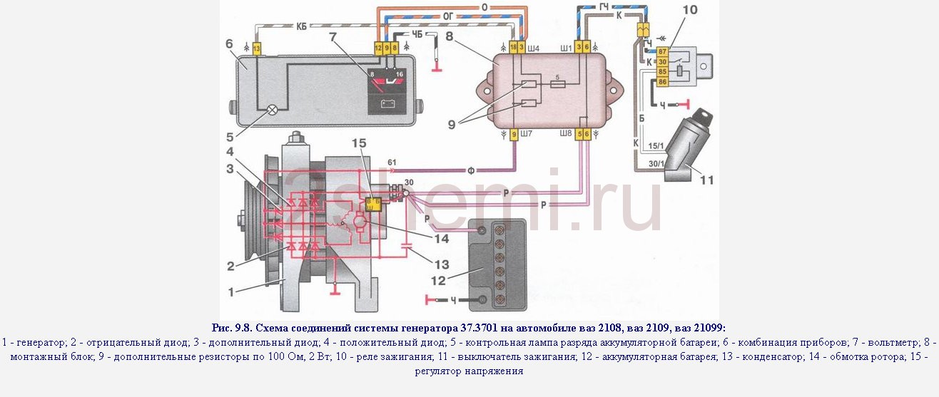
The wiring diagram of the 37.3701 generator is shown in Fig. 9.8. The voltage to excite the generator when the ignition is turned on is supplied to the “B” terminal through the pilot lamp 5 and resistors 9 connected in parallel. After starting the engine, the excitation winding is powered by three additional diodes installed on the rectifier unit. In this case, the current does not pass through the test lamp and it does not light up. The control voltage is supplied to terminal "B" of the voltage regulator directly from terminal "30" of the generator. Conclusion "Ш" of the regulator has no marking. Brush 13 is connected to it (see Fig. 9.6).
The wiring diagram of the 94.3701 generator is shown in Fig. 9.9. The voltage to excite the generator when the ignition is turned on is supplied to the D + terminal of the regulator (terminal D of the generator) through a test lamp 5 located on the instrument panel. When a VAZ 2108, VAZ 2109, VAZ 21099 ignition is turned on, the lamp should be on, and after starting the engine, it should go out if the generator is working properly. The bright burning of the lamp or its glow in full heat indicates malfunctions. After starting the engine, the excitation winding is powered by three additional diodes installed on the rectifier unit of the generator.
At the generator 37.3701 since 1996, the device of the voltage regulator and the brush holder has been changed. Now the voltage regulator is placed in a metal case and riveted to the brush holder (see Fig. 9.6, a), i.e. forms a non-separable unit with it. The new voltage regulator has no “B” pin, and only the “B” pin is supplied with voltage. According to their characteristics, the old and new voltage regulators are the same and assembled with a brush holder are interchangeable.
On small lots of cars VAZ 2108, VAZ 2109, VAZ 21099, generators made in Bulgaria, Slovenia or Germany can be installed. These generators are interchangeable with the 37.3701 generator in characteristics and installation dimensions, but differ somewhat in design. This section of the site describes only the domestic generator 37.3701 as the main one for cars of the VAZ 2108, VAZ 2109, VAZ 21099 family.
Rice. 9.9. Wiring diagram of the generator system 94.3701 on a car VAZ 2108, VAZ 2109, VAZ 21099:
1 - rechargeable battery; 2 - generator; 3 - mounting block; 4 - ignition lock; 5 - a control lamp of a charge of the storage battery, located on the dashboard WARNING
The "minus" of the storage battery must always be connected to the "mass", and the "plus" - to be connected to the terminal "30" of the generator. An erroneous reverse connection of the battery will immediately cause an increased current through the alternator diodes, and they will be damaged. It is not allowed to operate the generator with a disconnected rechargeable battery... This will cause transient overvoltages to occur at terminal 30 of the generator, which can damage the generator voltage regulator and electronic devices in the on-board network of the car VAZ 2108, VAZ 2109, VAZ 21099.
It is forbidden to check the generator's operability "for a spark" even by short-term connection of the generator terminal "30" with the "mass". In this case, a significant current flows through the diodes and the diodes are damaged. You can only check the generator using an ammeter and a voltmeter. It is not allowed to check the diodes of the rectifier unit of the generator with a voltage of more than 12 V or with a megohmmeter, since such a device has a voltage that is too high for diodes and the diodes will be broken during testing (a short circuit will occur). It is forbidden to check the electrical wiring of the car with a megohmmeter or a lamp supplied with a voltage of more than 12 V. If such a check is necessary, then first disconnect the wires from the generator. Check the insulation resistance of the stator winding with increased voltage only on the stand and always with the phase winding leads disconnected from the diodes. When electric welding of units and parts of the car body, the wires should be disconnected from all terminals of the generator and the battery.
USEFUL TIPS
If the alternator belt broke along the way, and you forgot the spare at home, you can temporarily replace the alternator belt with a 20 mm wide ring cut from the old car camera... To reduce current consumption when driving a VAZ 2108, VAZ 2109, VAZ 21099 with a faulty generator, if possible, turn off the radio, unnecessary lighting devices, a heater fan, heated glass, etc.
Rice. 9.6. Generator 37.3701 for cars VAZ 2108, VAZ 2109, VAZ 21099:
a - voltage regulator and brush assembly of generators of release since 1996; 1 - generator cover from the side of slip rings; 2 - a bolt of fastening of a rectifier unit; 3 - slip rings; 4 - ball bearing of the rotor shaft from the sides of the slip rings; 5 - capacitor 2.2 μF ± 20% to suppress radio interference; 6 - rotor shaft; 7 - wire of common output of additional diodes; 8 - terminal "30" of the generator for connecting consumers; 9 - plug "61" of the generator (common output of additional diodes); 10 - output wire "B" of the voltage regulator; 11 - a brush connected to the "B" terminal of the voltage regulator; 12 - voltage regulator; 13 - a brush connected to the "Ш" terminal of the voltage regulator; 14 - hairpin for fastening the generator to the tensioner; 15 - generator cover from the side of slip rings; 16 - fan impeller with generator drive pulley; 17 - pole tip of the rotor; 18 - bearing fastening washers; 19 - a distance ring; 20 - ball bearing of the rotor shaft from the drive side; 21 - steel sleeve; 22 - rotor winding (excitation winding); 23 - stator core; 24 - stator winding; 25 - rectifier unit; 26 - generator clamping bolt; 27 - buffer sleeve; 28 - bushing; 29 - clamping sleeve; 30 - output "B" of the voltage regulator; 31 - brush holder
Rice. 9.7. Generator 94.3701 for cars VAZ 2108, VAZ 2109, VAZ 21099:
1 - casing; 2 - output "B +" for connecting consumers; 3 - noise suppression capacitor; 4 - common output of additional diodes (connected to the output - "+" of the voltage regulator); 5 - holder of positive diodes of the rectifier unit; 6 - holder of negative diodes of the rectifier unit; 7 - conclusions of the stator winding; 8 - voltage regulator; 9 - brush holder; 10 - generator back cover; 11 - generator front cover; 12 - stator; 13 - stator winding; 14 - a distance ring; 15 - washer; 16 - conical washer; 17 - pulley; 18 - nut; 19 - rotor shaft; 20 - front bearing of the rotor shaft; 21 - beak-shaped pole pieces of the rotor; 22 - rotor winding; 23 - bushing; 24 - clamping screw; 25 - rear rotor bearing; 26 - bearing sleeve; 27 - slip rings; 28 - negative diode; 29 - positive diode; 30 - additional diode; 31 - terminal "D" (common output of additional diodes)
Rice. 9.8. Wiring diagram of the 37.3701 generator system on a VAZ 2108, VAZ 2109, VAZ 21099 car:
1 - generator; 2 - negative diode; 3 - additional diode; 4 - positive diode; 5 - control lamp of the battery discharge; 6 - instrument cluster; 7 - voltmeter; 8 - mounting block; 9 - additional resistors of 100 Ohm, 2 W; 10 - ignition relay; 11 - ignition switch; 12 - storage battery; 13 - capacitor; 14 - rotor winding; 15 - voltage regulator
Two types of generators are installed on VAZ 2109 cars. One part of the "nines" is equipped with generators of model 94.3701, and the other is equipped with Slovenian generators ААК-5102. Each of the presented types has its own characteristics. For example, the Slovenian AAK-5102 generator can be replaced with a 37.3701 generator of domestic production, which is usually installed on the VAZ 21083-20. The difference between the 94.3701 and 37.3701 generators lies only in the rotor, which drives the generator to work, namely, the first uses a poly V-belt, and the second uses a V-belt from the engine crankshaft pulley.
The device of the VAZ 2109 generator.
Generator 94.3701.

- shroud
- output "B +" for connecting consumers
- suppression capacitor
- common output of additional diodes
- holder of positive diodes of the rectifier unit
- holder for negative diodes of the rectifier unit
- stator winding leads
- voltage regulator
- brush holder
- generator back cover
- generator front cover
- stator
- stator winding
- distance ring
- washer
- cone washer
- screw
- rotor shaft
- front rotor shaft bearing
- beak-shaped rotor pole pieces
- rotor winding
- sleeve
- clamping screw
- rear rotor bearing
- bearing sleeve
- slip rings
- negative diode
- positive diode
- additional diode
- terminal "D"
Generator 37.3701.

- a - voltage regulator and brush assembly of generators from 1996
- rectifier mounting bolt
- slip rings
- ball bearing of the rotor shaft from the sides of the slip rings
- capacitor 2.2 μF ± 20% for RFI suppression
- rotor shaft
- common output wire for additional diodes
- terminal "30" of the generator for connecting consumers
- plug "61" generator (common output of additional diodes)
- output wire "B" of the voltage regulator
- brush connected to the "B" terminal of the voltage regulator
- voltage regulator
- brush connected to the "Ш" terminal of the voltage regulator
- stud for fastening the alternator to the tensioner
- generator cover from the side of slip rings
- fan impeller with alternator drive pulley
- rotor pole piece
- bearing retaining washers
- distance ring
- rotor shaft ball bearing, drive end
- steel sleeve
- rotor winding (field winding)
- stator core
- stator winding
- rectifier unit
- alternator pinch bolt
- buffer sleeve
- sleeve
- bushing
- output "B" of the voltage regulator
- brush holder
Technical characteristics of VAZ 2109 generators.
The highest recoil current at 13 V is 55 A for the 37.370 generator and 80 A for 94.3701.
At 37.370, the maximum regulated voltage is 13.6-14.6 V, and the engine-generator gear ratio is 1: 2.04. Its analogue, the generator 94.3701, has a maximum regulated voltage of 13.2-14.7 V, and the engine-generator gear ratio is 1: 2.4.
In addition to the technical characteristics in these models of the VAZ generator, there are differences in the size of the slip rings: in 94.3701, the rings have a smaller diameter than in 37.3701. They are made so to extend the life of the brushes and reduce the peripheral speed of rotation.
Connection diagram for generator model 37.3701.
When the ignition key is turned, the voltage for turning on the generator is connected to the output through the control lamp and resistors. After the engine is started, voltage is supplied to the excitation winding from three valves present on the rectifier unit. In this case, the control lamp does not light up, since no current passes through it. The main voltage is applied to the regulator terminal directly from the generator terminal.
Since 1996, changes have been made to the model 37.3701 generator, namely, the device of the regulator and the brush holder has been changed. From this moment, the voltage regulator is in a metal case and is attached to the brush holder. That is, they have become non-separable.
In addition to the considered generator model on VAZ 2109 cars, you can also see German, Bulgarian and, as mentioned above, Slovenian generators. All of them can be replaced with 37.3701. There are, of course, differences, but they are small and are related to the very design of the generator, but in terms of technical data and dimensions, they are the same.

- accumulator battery
- generator
- mounting block
- additional resistors 100 Ohm, 2 W
- ignition switch
- ignition relay
- instrument cluster
- battery discharge warning lamp
Wiring diagram for the generator VAZ 2109 (94.3701.).
To start the generator 94.3701 after turning on the ignition, the voltage goes to the output of the regulator, passing through the control lamp - it is located on the dashboard. After turning on the ignition, this light should light up, and after starting the engine, it should go out, if, of course, the VAZ 2109 generator is working properly. By the way, if the control light is on for too long, brightly or, conversely, at half the incandescence, then this means that there is some problem in the operation of the generator.
After starting the motor, the excitation winding receives voltage from three additional valves located on the rectifier unit of the generator.

- accumulator battery
- generator
- mounting block
- egnition lock
- battery charge indicator lamp located on the instrument panel
Attention!
Regardless of the model of the VAZ 2109 generator, one important rule must always be remembered: the "minus" of the battery must always be connected to the "ground", and the "plus" - to the terminal of the generator. Incorrect connection will cause overvoltage across the valves and damage them.
It is also forbidden to turn on the generator without a battery, as this will provoke a short-term overvoltage at the output of the generator, which will damage the regulator and, as a result, malfunction of the electronic devices in the car network.
The generator in cars is designed to generate electricity and charge the battery. If the normal operation of the car electric generator is disrupted, the battery begins to discharge and soon the car will stop starting at all - there will not be enough battery charge. This device consists of a three-phase diode bridge, which in turn has 6 silicon diodes. Electric voltage is created by excitation of the current rectifier at the moment when the rotor poles change under the stator windings. As the rotor rotates inside the machine stator, the rotor poles change. To increase the value of magnetic fluxes, the stator contains an electromagnetic exciting winding in the area of the magnetic cores. Wire marking and designation:
- P - pink.
- F - purple.
- O is orange.
- BW - black and white.
- KB - brown and white.
- ChG - black and blue.
- K - brown.
- H - black.
- B - white.
Wiring diagram for the VAZ-2101 generator

Structurally, the 2101 generator consists of the following main elements:
- Rotor- the movable part, rotates from the engine crankshaft. Has an excitation winding.
- Stator- the stationary part of the generator also has a winding.
- Front and back covers inside which bearings are installed. They have lugs for attaching to the internal combustion engine. A capacitor is located in the back cover, which is necessary to cut off the alternating current component.
- Semiconductor bridge- called "horseshoe" for the similarity. Three pairs of semiconductor power diodes are mounted on a horseshoe-shaped base.
- Pulley, on which the VAZ-2101 generator belt is put on. The belt is wedge-shaped (on modern cars, a multi-groove is used).
- Voltage regulator installed in the engine compartment, away from the generator. But still it must be considered part of the structure.
- Brushes mounted inside the generator and transmit the supply voltage to the excitation winding (on the rotor).
Wiring diagram for the VAZ-2106 generator

Wiring diagram for the VAZ-2107 generator

1 - rechargeable battery; 2 - negative diode; 3 - additional diode; 4 - generator; 5 - positive diode; 6 - stator winding; 7 - voltage regulator; 8 - rotor winding; 9 - capacitor for suppressing radio interference; 10 - mounting block; 11 - control lamp of the battery charge in the instrument cluster; 12 - voltmeter; 13 - ignition relay; 14 - ignition switch.
Wiring diagram for the VAZ-2108 generator
The VAZ-2108 generator has a rather massive stator winding, since it uses a wire of large cross-section. It is with its help that electricity is generated. The wire is wound evenly over the entire inner surface of the stator in the recesses specially provided for this purpose in the magnetic circuit. We should also talk about the latter separately. The middle section, the generator stator, consists of a set of thin metal plates pressed firmly against each other. Often they are boiled on the outside so that delamination does not occur.
Wiring diagram for the VAZ-2109 generator

- Alternator. Series 37.3701 or 94.3701 can be installed.
- Negative diode.
- Additional diode.
- Positive diode.
- The control lamp of the generator, it is also the discharge lamp of the battery.
- A combination of devices.
- Voltmeter.
- Relay and fuse box located in the engine compartment in the compartment between the engine and the passenger compartment.
- Additional resistors built into the fuse box.
- Ignition relay.
- Egnition lock.
- Accumulator battery.
- Capacitor.
- Rotor winding.
- The voltage relay is located in the engine compartment.
Wiring diagram for the VAZ-2110 generator
On cars VAZ-2110, 2111 and 2112, a 94.3701 generator was installed with a maximum output current of 80 Amperes and a voltage of 13.2-14.7 Volts.

We give a decryption generator connection diagrams for a dozen:
- 12V battery;
- generator 94.3701;
- mounting block;
- egnition lock;
- battery charge indicator lamp in the instrument cluster
How to check the generator yourself
How to check a vaz generator on the example of model 2109. Generator type 94.3701 alternating current, three-phase, with built-in rectifier unit and electronic voltage regulator, right rotation.

Alternator wiring diagram... The voltage to excite the generator when the ignition is turned on is supplied to the “D +” terminal of the regulator (“D” terminal of the generator) through a test lamp 4 located in the instrument cluster. After starting the engine, the excitation winding is powered by three additional diodes installed on the rectifier unit of the generator. The operation of the generator is monitored by a warning lamp in the instrument cluster. When the ignition is turned on, the lamp should be on, and after starting the engine, it should go out, if the generator is working properly. The bright burning of the lamp or its glow in the incandescent floor indicates a malfunction.
The "minus" of the storage battery must always be connected to ground, and the "plus" must be connected to the terminal "B +" of the generator. Failure to re-connect the battery will immediately cause increased current through the alternator valves and damage them.
It is not allowed to operate the generator with a disconnected battery. This will cause short-term overvoltages at the “B +” terminal of the generator, which can damage the generator voltage regulator and electronic devices in the vehicle's on-board network.
It is forbidden to check the generator's performance "for a spark" even by short-term connection of the "B +" clamp of the generator to ground. In this case, a significant current flows through the valves, and they are damaged.
Replacement and removal of an electric generator
The generator on a VAZ car is removed either for a complete replacement in case of failure or for repair work to replace defective parts. To carry out dismantling, prepare a standard set of tools, it is advisable to drive the car into the inspection pit.


- Disconnect the battery.
- Remove the protective rubber cap from the terminal "30" and unscrew the nut, remove the wires from the hairpin.
- Disconnect the block with wires from the generator connector.
- We loosen the tightening of fastening the generator to the adjusting plate, after which
we raise it all the way up to the cylinder block and remove the belt from the pulleys. - Completely unscrew the bolt securing the adjusting plate to the cylinder block, then unscrew the 2 bolts attaching the lower bracket to the block from the bottom of the car and remove the generator by pulling it out of the engine compartment.

The VAZ 2108 device, like any other vehicle, involves powering electrical circuits from a battery. So that the battery is constantly in good condition and does not let you down at the most inopportune moment, a generator is always paired with it. The battery is especially important at the time of engine ignition, while driving, when the car develops sufficient speed, the entire electrical circuit is powered from the generator.
When the question arises about connecting additional powerful electrical appliances to the car, it is very important to match their load with the permissible generator power. For this, it is important to know its technical characteristics. And if the indication of the lack of battery charge suddenly lights up, without understanding how the electrical charging circuit, voltage regulator and ignition are arranged, it is better not to even look under the hood.
Model at a glance
We should understand that the electrical circuit for connecting the generator is similar both in domestic cars and foreign cars and includes a standard set of components:
- the generator is a three-phase electric machine that generates, respectively, a three-phase electric current, converting mechanical energy into electrical energy;
- as a device for converting alternating voltage to direct voltage, a three-phase diode rectifier is usually used, connected according to the Larionov scheme;
- to protect the battery from overvoltage (the generator voltage directly depends on the engine speed), a voltage regulator is used in the circuit;
- the health of the charging circuit can be judged by the indicator light on the instrument panel;
- finally, the ignition key and the electric relay working with it in pair are necessary to turn on the generator and other electrical appliances in the car (which is why you should not leave the ignition on in the car for a long time, since the charging circuit also consumes current even when the car is just standing still).
The rotor of the generator is a movable structural element of an electric machine, the current is supplied to it through a special collector, along which graphite brushes travel. If the charging circuit of the VAZ 2108 generator is faulty, as evidenced by the corresponding indication on the instrument panel, first of all, the condition of the brushes should be checked. Mechanical faults rank second in terms of potential problems. These are rotor shaft bearings and a loose transmission strap.

Returning to how the electrical circuit works, we note that the voltage regulator can also fail you. To check this structural element, connect a test lamp or a multimeter set to measure a constant voltage in the range of up to 20 V to the regulator's current-collecting brushes, connect the negative terminal of the battery to the regulator's ground and supply + 12V to terminal B (V). If, by analogy, power the device with a voltage higher than 15 V, the control lamp will not light up.
If none of the above recommendations helps, you should remove the generator itself, check the diode rectifier, as well as the condition of the stator and rotor windings. For this purpose, it will not be superfluous for you to know the technical characteristics of the device on the VAZ 2108 and its possible versions. Read more in the next section of the article.
VAZ 2108 generator, design features and technical characteristics
The most common type of generator that can be found on the VAZ 2108 is the 37.3701 series model. Its main parameter is the supplied current. In our case, the maximum load is limited to 55 A (at 5000 rpm). The maximum regulated voltage is 14.6 V. The gear ratio from the engine to the generator has a multiplier of 2.04.
Some vehicles of the VAZ 2108 series are equipped with a generator of model 94.3701. A similar one can be found on a VAZ 2111 car. This electric car is much more powerful than the basic configuration of the "Eight" and can produce a current of up to 80 A in normal operation at 5000 rpm. The gear ratio from engine to generator has a multiplier of 2.4. The Slovenian version of this device is marked as AAK-5102, is completely interchangeable, but has a slightly different internal layout of parts.
Mechanical force from the crankshaft of the power unit is transmitted to the generator shaft using a wedge (for 37.3701) or poly-V (for 94.3701) strap. You can find out what kind of generator you have installed either from the passport for the car, or by reading the tag on the device itself. If none of the options presented is possible, you will be helped at the service station on a special test bench to help you find the “comrade”.