System of changing phases of gas distribution. Auto Reviews VVT I Phase System
10.07.2006
Consider here the principle of functioning of the system of the VVT-I second generation, which is now applied on most Toyotov engines.
VVT-I system (VARIABLE VALVE TIMING INTELLIGENT - changing phases of gas distribution) allows you to smoothly change the gas distribution phases in accordance with the operating conditions of the engine. This is achieved by turning the camshaft of the intake valves relative to the graft shaft in the range of 40-60 ° (at the corner of the rotation of the crankshaft). As a result, the moment of the opening of the inlet valves and the time of the "overlapping" (that is, the time when the exhaust valve is not yet closed, and the intake is already open).
1. Design
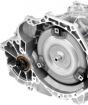
The VVT-I actuator is placed in the camshaft pulley - the drive body is connected to an asterisk or gear pulley, a rotor - with a camshaft.
The oil is supplied from one or another side of each of the rod petals, forcing it and the shaft itself is turned. If the engine is muled, then the maximum delay angle is set (that is, an angle corresponding to the latest opening and closing of the inlet valves). To immediately after launch, when the pressure in the oil line is still not enough to effectively control the VVT-I, there were no shocks in the mechanism, the rotor is connected to the housing of the locking pin (then the pin is pressed by the oil pressure).
2. Functioning
For the turning of the camshaft, the oil under pressure using an spool is sent to one of the sides of the rotor petals, simultaneously opens to the plums of the cavity on the other side of the petal. After the control unit determines that the camshaft occupied the desired position, both channels to the pulley overlap and it is held in a fixed position.
|
Mode |
№ |
Phase |
Functions |
Effect |
|
Idling |
|
The angle of rotation of the camshaft, corresponding to the very late start of the opening of the ink valves (the maximum delay angle). The "overlap" of the valves is minimal, the inverse flow of gases on the inlet is minimal. | Engine works more stable on idling, fuel consumption is reduced | |
|
|
The overlap of the valves decreases to minimize the return flow of gases to the inlet. | Increases engine stability | ||
|
|
The overlap of the valves increases, while decreasing "pumping" losses and part of the exhaust gases enters the inlet | Fuel efficiency improves, NOX emission decreases | ||
|
High Load, Rotation Frequency below average |
|
Early closing of intake valves is ensured to improve cylinders | Torque increases on low and medium turns | |
|
|
It is provided later to closing the inlet valves to improve the filling on high revolutions | Maximum power increases | ||
|
With low cooling fluid temperature |
- |
|
Mounted minimum overlap to prevent fuel loss | Stabilizes the increased speed of the idle rotation, improves efficiency |
|
When starting and stopping |
- |
|
Mounted minimum overlap to prevent exhaust gas from entering the intake | Improves engine launch |


3. Variations
The above 4-petal rotor allows you to change the phases within 40 ° (as, for example, on the engines of the ZZ and AZ series), but if you want to increase the angle of rotation (up to 60 ° in SZ) - 3-petal or workers cavities are applied.
The principle of operation and modes of operation of these mechanisms are absolutely similar, except due to the extended adjustment range it becomes possible to exclude overlapping valves at idle, at a low temperature or start.
In this blog, let us tell you in detail about the varieties of the Toyotovskaya shift system of the FUA gas distribution.
System VVT-I.
VVT-I is the branded system of the gas distribution mechanism from the Toyota corporation. From English Variable Valve Timing with Intelligence, which means the intellectual change in the phases of gas distribution. This is the second generation of the Toyota timing phase change system. Installed on cars since 1996.
The principle of operation is quite simple: the main control device is the coupling VVT-I. Initially, the valve opening phases are designed that good thrust is present at low revolutions. After the revs are significantly rising, and the oil pressure is also increasing with them, which opens the VVT-I valve. After the valve is open, the camshaft rotates to a certain angle relative to the pulley. The cams have a certain shape and when the crankshaft turns, the intake valves are revealed slightly earlier, and close later, which favorably affects the increase in power and torque on high revs.
VVTL-I system.
VVTL-I is the branded system of the TMC gas distribution mechanism. From English Variable Valve Timing and Lift with Intelligence, which translated means an intelligent change in the phases of gas distribution and lifting valves.
The third generation of the VVT \u200b\u200bsystem. Distinctive feature From the second generation VVT-I lies in the English word Lift - lifting valves. In this system, the camshaft is not simply rotated in coupling vvt. Regarding the pulley, smoothly adjusting the opening time of the ink valves, but even during certain conditions of operation, the engine lowers the valve deeper into the cylinders. Moreover, the lifting of the valves is implemented on both camshafts, i.e. For intake and exhaust valves.
If you carefully look at the camshaft, then you can see that for each cylinder and for each pair of valves there is one rocker, according to which two cam is performed at once - one ordinary, and the other enlarged. Under normal conditions, the enlarged cam worked out in idle, because In the rocker, under it is provided, the so-called slippers, which freely enters the inwards of the rocker, thereby not allowing a large cam to transmit the power of pressing on the rocker. Under the slipper is a locking pin, which is driven by oil pressure.
The principle of operation is as follows: With an increased load on high speed, the ECU applies a signal to an additional VVT valve - it is almost the same as on the coupling itself, with the exception of small differences in shape. As soon as the valve opened, the oil pressure is created in the highway, which mechanically affects the lock pin and shifts it towards the base of the slipper. All, now slippers are blocked in the rocker and does not have free stroke. Moment from a large cam begins to be transferred to the rocker, thereby lowering the valve deeper into the cylinder.
The main advantages of the VVTL-I system are that the engine is well pulling on the bottoms and focuses on top, fuel efficiency improves. The disadvantages are reduced environmental friendliness, which is why the system in such a configuration has not long existed.
DUAL VVT-I system.
Dual VVT-I is the branded system of the TMC gas distribution mechanism. The system has general principle Working with the system VVT-I, but common to the distributional shaft of the exhaust valves. In the head of the cylinder block on each pulley of both camshafts, VVT-I couplings are located. In fact, this is a regular Dual VVT-I system.
As a result, the engine ECU is now managing the opening time inlet and exhaust valves, allowing you to achieve a large fuel efficiency as low turns and high. The engines turned out to be more elastic - the torque is distributed evenly throughout the engine revolutions. Given the fact that Toyota decided to abandon the height of the lifting of the valves as in the VVTL-I system, therefore Dual VVT-I is deprived of its lack of concluding in relatively low ecology.
For the first time, the system was installed on the 3S-GE engine of the RS200 Altezza car in 1998. Currently, it is installed almost on all modern Toyota engines, such as the V10 LR series, V8 series UR, V6 series GR, AR and Zr series.
VVT-IE system.
VVT-IE is the brand system of the Toyota Motor Corporation gas distribution mechanism. From English Variable Valve Timing - IntelliGent by Electric Motor, which translated means an intelligent change in the phases of gas distribution using an electric motor.
Its meaning is exactly the same as the VVTL-I system. The difference is to implement the system itself. The camshafts are deflected on a certain angle for ahead or delay relative to asterisks with an electric motor, and not by oil pressure, as on previous VVT models. Now the operation of the system does not depend on the speed of the engine and operating temperature Unlike the VVT-I system, which is not capable of working at low engine speeds and without reaching the engine operating temperature. On low oil pressure, small and it is not capable of moving the vvt clutch blade.
VVT-IE does not have drawbacks previous versionsbecause It does not depend on the engine oil and its pressure. Also, this system has another plus - the ability to accurately position the displacement of the camshafts depending on the operating conditions of the engine. The system starts its work starting from the start of the engine startup and before its complete stop. Her work contributes to high ecology modern engines Toyota, maximum fuel efficiency and power.
The principle of operation is as follows: The electric motor rotates along with the camshaft in the mode of its rotation speed. If necessary, the electromotor is either slowed down, or vice versa accelerates relative to the colleagne sprocket, thereby making the camshaft offset to the desired angle, ahead of or delaying the gas distribution phase.
The VVT-IE system first debuted in 2007 on Lexus LS 460, installed in the 1UR-FSE engine.
Valvematic system.
Valvematic is an innovative gas distribution system toyota companywhich allows you to smoothly change the lifting height depending on the operating conditions of the engine. This system is applied to gasoline engines. If you figure it out, the ValveMatic system is none other than the improved VVTI technology. In this case, the new mechanism works in conjunction with the already familiar system for changing the opening time of the valves.
With help new system The ValveMatic engine becomes more economical to 10 percent, since this system controls the amount of air to the cylinder, and provides a lower carbon dioxide content at the output, thereby increases the engine power. The VVT-I mechanisms that perform the main function are placed inside the camshafts. The housings of the drives are connected to the gear pulleys, and the rotor with camshafts. The oil envelops either one side of the rotor petals, or the second, thereby forcing the rotor and the shaft turn. In order for the engine startup, the rotor does not appear, the rotor makes the locking pin to the body, then the pin departs under the pressure of the oil.
Now about the advantages of this system. The most significant of them is fuel economy. As well as thanks to the ValveMatic system, the engine power increases, because Permanent adjustment of the lifting height of the valve at the time of opening and closing the ink valves. And of course, do not forget about the environment ... The Wavematic system significantly reduces carbon dioxide emissions into the atmosphere, up to 10-15% depending on the engine model. Like any technological innovation, the Valvematic system also has negative reviews. One of the reasons for such reviews is outsunction in the work of the DVS. This sound resembles the Cocan of the poorly adjusted valve gaps. But it passes after 10-15 thousand. km.
At the moment, the Valvematic system is installed on Toyota cars with 1.6, 1.8 and 2.0 liters engines. For the first time the system was tested on toyota cars Noah. And then installed on the engines of the Zr series.
Systems for changing the phases of gas distribution became a revolution for engines internal combustionAnd they became popular thanks to the Japanese models of the 90s. But how do the most famous systems differ in operation from each other?
Internal combustion engines from their very creation were not as efficient as possible. The average efficiency of such motors is 33 percent - the rest of the energy created by the combusting fuel-air mixture is wasted. Therefore, any way to make the engine is more energy efficient, and the system of changing the gas distribution phases has become one of the most successful solutions.
The system changes the gas distribution phases (the moment in which each valve opens and closes during the operating cycle), their duration (the moment when the valve is open) and the rise (as far as the valve can open).
As you know, the inlet valve in the engine runs into the cylinder the fuel-air mixture, which is then compressed, is burned and pushed into the opening valve opening. These valves are driven by the pushers that control camshaft, using a set of cams for the perfect closure and opening ratio.

Unfortunately, ordinary camshafts are done in such a way that you can control only the opening of the valves. This is the problem, since for maximum valve efficiency, it should be closed and open differently on different engine speeds.
For example, at high speed operation of the intake valve, you need to open a little earlier due to the fact that the piston moves so quickly that it does not allow to get inside with a sufficient amount of air. If the valve is open a little earlier, more air will get into the cylinder, which will increase the combustion efficiency.
Therefore, instead of a compromise between camshafts for large and small revolutions, a system of changing the phases of gas distribution recognized by one of the most effective in this area appeared. Different companies in different ways interpreted this technology, so let's figure out with the most popular of them.


Vanos (or Variable Nockenwellensteuerung) - Attempt by BMW Create a system for changing the gas distribution phases, and for the first time it was applied on the M50 motor installed on a 5-series in the 90s of the last century. It also uses the principle of delaying or ahead of the interaction of the GDM mechanisms, but using a toothed transmission inside the camshaft pulley, which moves together or against the camshaft, changing the phases of operation. This process is controlled electronic block Management that uses oil pressure to move the gear forward or backward.
As in the case of the other systems, the gear movement moves forward in order to open the valve a little earlier, increasing the amount of air entering the cylinders and increasing the output power of the engine. In fact, BMW first presented a single Vanos, which worked only on inlet camshaft In certain modes on different engine speed. The German company later developed a system with two Vanos, which is considered more advanced, as it affects both camshafts, and also regulates the position throttle valve. Double Vanos was created for S50B32, which was put on the BMW M3 in the Body E36 ,.

Now almost every large manufacturer has its own name for the gas distribution phase system - Rover is VVC, Nissan - VVL, and Ford has developed VCT. And there is nothing surprising in this, given that this is one of the most successful finds for internal combustion engines. Thanks to her, manufacturers were able to reduce consumption, and increase the capacity of their motors.
But with the arrival of pneumatic valves, these systems will go on peace. However, now - just their time.
The VVT-IW circuit is the timing chain drive on both camshafts, a phase change mechanism with bladed rotors on an inlet and outskins, an extended inlet adjustment range. It was used on 6A-FSE engines, 8R-FTS, 8NR-FTS, 2GR-FKS ...
System VVT-IW. Variable Valve Timing Intelligent Wide) allows you to smoothly change the gas distribution phases in accordance with the operating conditions of the engine. This is achieved by turning the camshaft inlet valves relative to the drive asterisk in the range of 75-80 ° (over the corner of the crankshaft).
Advanced, compared to the usual VVT, the range is mainly at the delay angle. On the second camshaft in this scheme, the VVT-I drive is installed.
The VVT-I system (VARIABLE VALVE TIMING Intelligent) allows you to smoothly change the phases of the gas distribution in accordance with the operating conditions of the engine. This is achieved by turning the camshaft of the exhaust valves relative to the drive asterisk in the range of 50-55 ° (over the corner of the crankshaft).
Sharing VVT-IW on the inlet and VVT-I on the release provides the following effect.
1. Start mode (EX - advance, in - intermediate position). To ensure reliable startup, two independent retainers retaining the rotor are used in an intermediate position.
2. Partial load mode (EX - delay, in - delay). It is possible to operate the engine along the Miller / Atkinson cycle, while the pump losses decrease and efficiency improves. Read more -.
3. Mode between medium and high load (EX - delay, in - ahead). It is ensured by the TN mode. Internal recycling of exhaust gases and improves the conditions of issue.
The control valve is built into the central drive bolt (sprocket) to the camshaft. In this case, the control oil channel has a minimal length, providing maximum speed Response and trigger at low temperatures. The control valve is driven by the VVT-IW valve plunger.
The design of the valve allows you to independently control the two locks, separately for the lifting and delay circuits. This is a challenge to fix the rotor in the intermediate position of the VVT-IW control.
E / M VVT-IW valve is mounted in the cap circuit lid and is connected directly to the actuator in the inlet camshaft phases.
Advance
Delay
Holding
VVT-I drive
A VVT-I void rotor (traditional or new sample is installed on the graduation camshaft (traditional or new sample, which is built into the central bolt). When the engine is shoved, the lock holds the camshaft in the maximum advance position to ensure normal start.
The auxiliary spring applies the moment in the direction of ahead to return the rotor and reliable triggering of the lock after turning off the engine.
The control unit by means of an e / m valve controls the oil supply in the lifting cavity and VVT drive delay based on the camshaft position sensor signals. On the shredded engine, the spool moves the spring in such a way as to ensure the maximum advance angle.
Advance. E / M The valve across the ECM signal switches to the advance position and shifts the spool of the control valve. Motor oil Under pressure enters the rotor on the side of the advance cavity, turning it together with the camshaft in the direction of the advance.
Delay. E / M The valve on the ECM signal switches to the delay position and shifts the spool of the control valve. Motor oil under pressure enters the rotor on the side of the delay cavity, turning it together with the camshaft in the delay direction.
Holding. ECM calculates the desired advance angle in accordance with the conditions of movement, and after setting the specified position, switches the control valve to a neutral position until the next change in external conditions.
VVTI is a system for changing the phase values \u200b\u200bof gas distribution. If we translate this abbreviation with of English languageThis system is responsible for the intelligent phase displacement. Now on modern japanese engines The second generation of mechanisms has been established. And for the first time Vvti began to install on cars since 1996. The system is a coupling and a special vvti valve. The latter performs the role of the sensor.
VVTI VVTi VVTi Valve Device
The element consists of a housing. In the outer part there is a control solenoid. It is responsible for the movement of the valve. Also in the device there are sealing rings and a connector for connecting the sensor.
General principle of system operation
The main control device in this system of shift of the phase of gas distribution is the VVTI coupling. By default, the engine developers designed the valve opening phases so as to get a good traction on low motor turnover. As the rotation increases, the oil pressure is growing, due to which VVTI valve opens. Toyota-Camry and its 2.4 liter engine works on the same principle.
After this valve opens, the camshaft turn into a certain position relative to the pulley. The cams on the shaft have a special form, and in the process of rotation of the element, the inlet valves will be opened a little earlier. Accordingly, it is later closed. This should best affect the power and torque of the engine at high speed.
Detailed job description
The main control mechanism of the system (and this clutch) is installed on the motor camshaft pulley. The body is connected to the asterlert or the rotor connects directly to switchgear. Oil from is served from one or two sides to each rotor petal on the coupling, forcing the distribution shaft to rotate. When the engine is not running, the system automatically sets the maximum delay angles. They correspond to the very late opening and closing of the inlet valves. When the motor starts, the oil pressure is not strong enough to open the VVTI valve. To avoid any blows in the system, the rotor connects to the housing of the coupling with a pin, which, with the increase in pressure, the lubricant will be pressed by the oil itself.

The operation of the system is carried out by means of a special valve. By signal with the computer, an electric magnet with a plunger will begin to move the spool, thereby skipping the oil in one or in another direction. When the motor is stopped, this spool moves at the expense of the spring so as to set the maximum delay angle. To rotate the camshaft on a certain angle, oil under high pressure Through the spool is supplied to one of the sides of the petals on the rotor. Simultaneously with this, the special cavity opens. It is located on the other side of the petal. After the computer understands that the distribution shaft will be turned to the desired angle, pulley channels overlap and it will be left further in this position.
Typical symptoms of VVTI system problems
So, the system must change the phases of the work if any problems arise with it, then the car will not be able to function normally in one or several operating modes. You can select multiple symptoms that will affect faults.

So, the car does not hold idling on the same level. This suggests that the vvti valve does not work as needed. Also about various malfunctions in the system will say "braking" of the engine. Often, when problems with this mechanism, the phase change lacks the possibility of working on low revs. More about problems with the valve can say error P1349. If on a heated force aggregate High idle speed, the car does not go at all.
Possible Causes Valve Fault
The main causes of valve faults is not so much. You can allocate two, which are especially common. So, the VVTI valve may fail due to the fact that there are cliffs in the coil. In this case, the element will not be able to react to the transmission of voltage. Fault diagnostics is easily implemented using a measurement check for the resistance of the sensor coil.

The second reason why VVTI valve (Toyota) works incorrectly or does not work at all - it is jealous in stock. The reason for such jams can be a banal dirt that has accumulated in the channel over time. It is also possible that the sealing gum inside the valve is deformed. In this case, it is very easy to restore the mechanism - it is enough to clean the dirt from there. This can be done by wrinkling or dumping the element in special fluids.
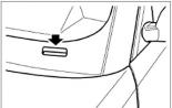
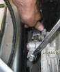
How to clean the valve?
Many faults can be cured by cleaning the sensor. First you need to find VVTI valve. Where this element is located, you can see in the photo below. He is encountered in the picture.

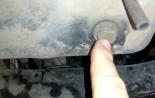
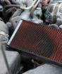
Cleaning can be carried out using liquids for cleaning carburetors. To fully clean the system, remove the filter. This element is under the valve - it is a plug in which there is a hole under the hexagon. The filter also needs to be purified by this liquid. After all operations, it remains only to collect everything in the reverse order, and then install without resting at the same time in the valve itself.
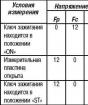
How to check VVTI valve?
Check if the valve works, very simple. For this, the voltage in 12 V. is submitted to the sensor contacts, it is necessary to remember that it is impossible to keep the element under voltage for a long time, since it cannot work in such modes so much time. At the time of supplying the voltage, the rod will draw inside. And when the chain dispels, it will return back.

If the rod moves easily, the valve is fully working. It only needs to rinse, lubricate and can be operated. If it does not work as needed, then the repair or VVTI valve replacement will help.
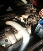
DIY repair of the valve
First dismantle the regulating bar of the generator. Then remove the fastener of the hood lock. It will open access to the axial bolt of the generator. Next, we unscrew the bolt that holds the valve itself, and remove it. After filter is removed. If the last element and valve are dirty, then these parts are cleaned. Repair is an inspection and lubrication. You can also replace the sealing ring. More serious repairs are not possible. If the item does not work, easier and cheaper to replace it with a new one.
Self Replacement VVTI Valve
Often cleaning and lubrication does not provide the necessary result, and then the question arises full replacement Details. In addition, many car owners after replacement argue that the car began to work much better and the fuel consumption decreased.

To begin with, they remove the regulatory bar of the generator. Then remove the fastener and get access to the generator bolt. Pubrip the bolt to which is held the desired valve. The old element can be pulled out and throw away, and the old one put a new one. Then twist the bolt, and the car can be operated.
Conclusion
Modern cars at the same time and good, and bad. The bad they are the fact that not every operation associated with repair and maintenance can be performed independently. But it is possible to replace this valve with your own hands, and this is a big plus to the Japanese manufacturer.