Hoisting machines. Bogachev V.N.
Lecture 1 General information about lifting equipment Purpose of the lesson: To study the purpose and composition of lifting equipment, mechanisms and elements of lifting machines, general information about cranes Educational questions: 1. Purpose and composition of lifting equipment 2. Mechanisms and elements of lifting machines 3. Automobile cranes 4. Bridge cranes
Literature: 1. "Rules for the device and safe operation hoisting cranes "PB (approved by the Decree of the Gosgortekhnadzor of the Russian Federation dated 098) 2." Intersectoral rules on labor protection during loading and unloading and placement of goods "POT RM (approved by the decree of the Ministry of Labor and Social Development Russian Federation dated March 20, 1998 16) 3. Fedoseev V.N. Safety devices and devices for hoisting machines: Handbook. - M .: Mechanical engineering, - 320s. 4. Naboka E.M. Lifting equipment: textbook. - Perm: PVI RV, p.

Purpose and composition of lifting equipment Lifting equipment is an integral part of technological equipment and is designed to perform loading and unloading, assembly and dismantling works. Lifting equipment includes lifting machines (GPM) and lifting devices (GZP). PMGs are designed for lifting and moving various loads in space. GZP are used to connect the PMG hook with the load being lifted (load slinging) PMGs are divided into three groups: the simplest lifting machines (jacks, winches, hoists), hoists, lifting cranes (boom and bridge types). on the hook of the crane, and removable, attached to the load being lifted. SPGs are not part of the PMG and are independent reusable products

Jacks are designed for lifting loads to a low height (up to 1.0 m). They are used for repair and installation work. The jacks can be driven manually or by machine. By the type of mechanism that allows you to get a gain in strength, jacks are divided into screw, rack, hydraulic and chamber Jacks: a - screw: 1-nut; 2-screw; b - rack and pinion: 1-toothed rack; 2-gear associated with the handle; в - hydraulic: 1-plungers; d - chamber: 1-supply of compressed air from a compressor, cylinder, foot pump

Winches are designed for straight-line movement of loads. There are lifting winches used for vertical lifting of a freely suspended load, and traction winches, which are used to move a load or a truck with a load in the horizontal direction Winches: a - traction: 1-drive; 2-drum; 3-rope; 4-load; b - lifting: 1-drive; 2-drum; 3-rope; 4-load; 5-deflection block


The hoists are lifting suspended winches. Mobile hoists are equipped with mechanisms for moving along overhead tracks. The hoists are part of the crane beams as a lifting mechanism. Waistline: a - manual: 1-beam; 2-hand winch; 3-chain; b - mobile electric: 1-beam; 2-electric winch

Hoists are hoisting devices of cyclic action for lifting loads and people in special load-carrying devices (cages, cabins, platforms) Hoists: a - mine: 1-winch; 2-cabin (cage); 3-shaft; b - rack-mountable: 1-deflecting block; 2-cargo platform; 3-rack; 4-winch

Hoisting cranes are hoisting machines of cyclic action, designed to lift and move in space various loads suspended by means of a hook. These are the most common PMGs with a very diverse design Classification of cranes


Main mechanisms of hoisting machines The functional purpose of the PMG is to move the load from one point of the working space to another. It is quite obvious that for this the PMG must be able to move the load in three mutually perpendicular directions, i.e. have three portable degrees of mobility of the load-gripping body (hook). In jib cranes, this is achieved by a load lifting mechanism (MPG), a mechanism for changing the boom outreach (MIVS) and a platform swing mechanism (MPP). In bridge cranes, three portable degrees of hook mobility are provided by a load lifting mechanism (MPG), a bridge movement mechanism (MPM) and a movement mechanism cargo trolley(MPGT) Degrees of mobility of the load-gripping body: a - jib crane: 1 - boom; b - overhead crane: 1 - cargo trolley; 2 - bridge

Structural diagrams of mechanisms of lifting machines. Structural diagram: a - MPG and MIVS: 1,3 - brake; 2 - engine; 4, 6-clutches; 5 - reducer; 7-reel; 8 - cargo (boom) chain hoist; b - MPP: 1 - brake; 2-engine; 3, 5 - couplings; 4 - reducer; 6 - gear wheel; 7 - ring gear ring; c - MPM and MPGT: 1 - brake; 2 - engine; 3, 5 - couplings; 4 - reducer; 6 - running wheel; 7 - rail

Elements of hoisting machines are hoisting bodies, steel ropes, blocks, hook suspensions, pulley blocks. A load-gripping body is a device included in the PMG for suspending and grabbing a load. The most widespread are cargo hooks Hooks Hooks: a - one-horned: 1-shank, 2-safety lock, 3-hook mouth; b - two-horned


Polyspast is a system consisting of movable and fixed blocks, bent by a rope. A block whose axis moves in space is called movable, and a block whose axis does not move in space is called stationary. Distinguish between cargo and boom pulley blocks. The cargo chain hoist is part of the MPG, and the boom one is part of the MIVS Polyspast: a - single: 1-rope; 2-drum; 3-stationary part of the PMG structure; 4-cutting drum; b - double: 1- rope; 2-drum; 3-leveling block; 4-way cutting of a drum


The main parameters of truck cranes are values that characterize technical capabilities Boom reach L - horizontal distance from the axis of rotation of the slewing part of the crane to the center of the hook mouth. The outreach is not constant, it depends on the length of the boom and the angle of inclination. Hook lifting height H is the distance from the crane parking level to the center of the hook mouth, which is in the extreme upper position. The value of H depends on the length and angle of inclination of the boom Hook lowering depth h - the distance from the crane parking level to the center of the hook mouth, which is in the lowest position


The speed of lifting and lowering the load - the speed of vertical movement of the load Landing speed - lowest speed lowering of the maximum permissible load during installation or stacking Turntable rotation speed - the number of rotations of the turntable per unit of time Operating speed of the crane - the speed of the crane on the working platform with the boom equipment in the working position and with a suspended load, if movement with a load is allowed on the hook Transport speed of the crane - the speed of the crane, the boom equipment of which is in the transport position.Total weight of the crane - the weight of the crane with boom equipment and counterweight when fully filled with fuel and lubricants The main overall dimensions of the crane: maximum length, height, width and distance between outriggers. dimensions determine the ability to work and move the crane in confined spaces


Diagram of a double-girder overhead traveling crane of a supporting type Double-girder overhead traveling crane of a supporting type: 1 - main beams; 2 - end beams; 3 - separate drive of the travel wheels of the bridge movement mechanism; 4 - cargo cart; 5 - the main mechanism for lifting the load; 6 - auxiliary mechanism for lifting the load; 7- the mechanism of movement of the cargo trolley; 8 - control cabin; 9 - trolls; inspections 10 - a cabin for trolleys; 11 - flexible electric cable; 12 - wire holding the electric cable

- See also:
- Bortiakov D.E., Orlov A.N. Special hoisting machines (Document)
- Special lifting machines. Portal, ship and floating cranes (Document)
- Course Project - Pavement Crane (Coursework)
- Yu.V. Navarsky Hoisting machines (Document)
- Alexandrov M.P. Hoisting machines (Document)
- Alexandrov N.P., Kolobov L.N., Lobov N.A. etc. Hoisting machines (Document)
- Kuzmin V.V. Calculation and design of vacuum machines and installations (Document)
- Savitsky V.P. Hoisting machines (course design) (Document)
- RTM 24.090.32-77 Hoisting cranes. Steel structures. Calculation methods (Document)
- Course project - Crane with a slewing tower (Course project)
- Zel'dovich E.A. Design and Maintenance of Romayor Machines (Document)
- Abstract - Hoisting machines. Bridge cranes (Abstract)
n1.doc
Technological hoisting machines.
Under technological lifting machines (technological PMM) - we mean lifting machines used in technological process engineering production.Chapter 1. Overview of designs of lifting machines.
There are two groups of lifting machines: machines with flexible load suspension and machines with rigid load gripping.§one. Hoisting machines with flexible load suspension.
Dignity.
Possibility of lifting loads to very high heights.
Steel wire ropes are used as a flexible load element. The rope, being an elastic element, softens the impact of the load.
The mechanism for lifting the load can be completed, to a large extent, from standard and normalized elements.
The need for rigging operations (mooring and uncoupling of cargo).
When moving horizontally, the load swings on the rope, therefore, an increase in the acceleration and deceleration time and a decrease in the speed of movement are necessary.
Tali.
Figure 1.1, a shows one of the options for the construction of the hoist,
but
in fig. 1.1, b - appearance hoist.

but)
From the electric motor 1, the rotation is transmitted through the clutch 2 to the high-speed shaft 4 of the toothed cylindrical two-stage coaxial gearbox and then through two pairs of gears 15.10 and 8.9 to the rope drum 13. The drum 13 is installed in the body 5 of the hoist on two radial bearings 3 and 6 When the drum rotates in one direction or another, the rope 12 is wound on the drum and lifts the hook suspension 7 or unwinds from the drum and lowers the suspension. At the right end of the shaft 4 is installed disc brake 11. The hoist is suspended from a trolley 16, which on wheels 14 moves along a suspended I-beam 17.
Stationary slewing cranes.
2.1. Wall mounted slewing cranes.
Cranes are available with constant and variable overhang, with truss and girder metal structures. Turning the crane is usually manual. In fig. 1.2 shows a wall mounted fixed reach jib crane with a truss type steel structure.
Fig.1.2.1 –thrust bearing; 2,4– radial bearings; 3 –metal structure 5– crane column; 6 - lifting mechanism; 7 - rope; 8 - deflecting block; 9 - hook suspension; 10 - handle for turning the crane.
Column 5 of the crane is installed in two supports. The lower support is combined with radial 2 and thrust 1 bearings, and the upper support is floating with radial bearing 4.
Self-aligning bearings are usually used in the bearings of slewing cranes, which can compensate for misalignment and mutual misalignments of the axes. mounting holes in the support housings.
Figure 1.3 shows a beam-type, variable overhang wall-mounted jib crane. Hoist 2 moves along the arrow of the metal structure 1.

Figure 1.3.
2.2. Rotating column cranes.

Figure 1.4 shows a crane with a rotating column 7, welded with a beam-type boom 9. A hoist 10 moves along the boom 9. The lower support of the column 7 is combined with radial 11 and thrust 12 bearings, and the upper support is floating with a radial bearing 8.
The crane is turned by a mechanism consisting of an electric motor 1, a clutch 2, a brake 3, a worm gear 13, a safety clutch 5 and an open gear transmission 4, 6. Gear 4 is installed on the low-speed shaft of the gearbox 13, and the gear 6 is on the column 7.
The service area for a full-turn crane is a ring, for a part-turn crane it is a part of the ring.
2.3. Fixed column cranes.
Cranes are available with constant and variable overhang, with truss and beam-type metal structures, full-revolving and part-revolving; the rotation is carried out manually or by a mechanism.

Figure 1.5 shows a fixed column crane with a constant overhang and a beam-type steel structure. The metal structure consists of a rotating column 7 and a beam boom 10 fastened to it. The metal structure rests on a fixed column 6.
The upper support is combined with radial 9 and thrust 8 bearings, and the lower support is floating with a radial bearing 5. Much more often, the lower support is made in the form of rollers rolling along a fixed column 6.
The crane is turned by a mechanism consisting of a gear motor 1, a safety clutch 2 and an open gear transmission, including a gear 3 and a gear 4. Gear 3 is installed on the output shaft of the gear motor 1, and the wheel 4 is on the column 6. Service area for a full-turn crane - a narrow ring, for a part-turn crane - a part of a narrow ring.
Bridge type cranes.
3.1. Single girder cranes with electric hoist (girder cranes).
The diagram of the crane beam is shown in Fig. 1.6.
The main girder 2 (I-beam) is welded with two end girders 1. An electric hoist moves along the main girder 3. The crane itself moves along the shop on wheels 5 on rails 4. The service area is a rectangle elongated along the shop.
3.2. Electric bridge cranes.
Electric overhead traveling cranes have a higher lifting capacity, have a larger span, but are more complex than jib cranes. In modern designs, one main box-section beam is usually made. The rails are laid on the main beam, along which the trolley moves, which carries the load lifting mechanism. Bridge cranes are rarely used as technological hoisting machines.3.3. Gantry and semi-gantry cranes.
These cranes are mainly used for open material storage.§2. Hoisting machines with rigid load gripping.
Dignity.
Lack of rigging operations, because the load is grabbed with a special gripper, and the operator controls the machine from the remote control.
When moving horizontally, the load does not swing.
Figure 1.7, a shows a rotary hydraulic crane. A rotating column 5 is installed in the stationary column 4. The upper support of the column 5 is made combined with radial 6 and thrust 7 bearings, and the lower support is floating with a radial bearing 3. An option of the upper support with one angular contact bearing is possible.

From the hydraulic motor 1, the rotation is transmitted through the coupling 2 to the column 5. The swing of the boom 9 is carried out by the hydraulic cylinder 8, the gripping of the load - the gripper 12, and the vertical movement of the load - the telescopic hydraulic cylinder 11. When the boom 9 swings, the hydraulic cylinder 11 deviates from the vertical position. To eliminate this drawback, an auxiliary hydraulic cylinder 10 is used, the operation of which is coordinated with the operation of the hydraulic cylinder 8 in such a way that the hydraulic cylinder 11 is always in a vertical position. The vertical position of the hydraulic cylinder 11 can be ensured by making the boom 9 in the form of a pantograph (Fig. 1.7, b).
Figure 1.8 shows a mobile hydraulic crane.
The main girder 1 of the box section is welded with two end girders 2. The carriage moves along the main girder on three pairs of rollers 3, 6 and 7 4. The vertical movement of the load is carried out by a telescopic hydraulic cylinder 5. The crane itself moves along the shop on wheels 9 on rails 8.

Send your good work in the knowledge base is simple. Use the form below
Students, graduate students, young scientists who use the knowledge base in their studies and work will be very grateful to you.
There is no HTML version of the work yet.
You can download the archive of the work by clicking on the link below.
Similar documents
Hoisting and transporting machines, their parts. Calculation of the main parameters of the crane lifting mechanism, as well as the movement of the hoist. Calculation of the crane metal structure. Lubrication of valve assemblies and parts, selection and justification of the oil required for this.
term paper, added 11/22/2013
Application and versatility of the use of lifting machines, the role of their automation as an integral part of production. Basics of overhead crane trolley design. Choice of hook block, rope, motor, gearbox, brake standard size.
term paper, added 07/28/2010
Acquaintance with the main types of mechanical handling equipment used in warehouses. Consideration of the principles of operation of lifting machines for vertical and sharply inclined movement. The use of elevators and lifts.
abstract added on 10/21/2014
The essence of complex mechanization in construction. Basic information about hoisting machines. Tower cranes: their layout, design and installation principles at the construction site. Calculation of load, own and wind stability of a tower crane.
term paper added 02/17/2013
Construction of an overhead crane. Mechanisms of its movement and lifting. Calculation of the basic kinematic parameters for the selection of the traction element, dimensions and shapes of the drum, electric motor, gearbox and brake. Limiters of the path of movement of the crane and cargo trolley.
term paper, added 04/18/2015
Calculation of time modes of operation of machines, numbers technical services and repairs. Building the structure of the repair cycle of the machine. Determination of the time of bringing machines into service and repair for a tower crane, an excavator, a jib crane and a bulldozer.
term paper added 03/01/2017
The device, parameters, modes of operation of the mechanisms of hoisting machines. Calculation of parameters and development of structures for lifting and movement of an overhead crane. Working conditions and general technical specifications electrical equipment of hoisting machines.
term paper, added 02/15/2016
Calculation of load lifting mechanisms, trolley and crane movement, strength of metal structures. Choice of brakes, bearings and couplings. Power calculation and selection of gear motor. Checking the electric motor according to the start condition. Development of a hydraulic drive for an overhead crane.
thesis, added 07/07/2015
-
 The procedure for assigning a class to drivers and establishing a premium for class - labor relations - catalog of articles - higher education What determines the class
-
 Boxer engine: types, device and principle of operation
-
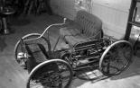 Henry Ford. History of success. Henry Ford success story Working by vocation
-
 The story of a great engineer