UAZ Car Ignition System
UAZ Car Ignition System
TO Manager:
UAZ
UAZ Car Ignition System
Device
The ignition system circuit is shown in Fig. 2. The ignition system includes: rechargeable battery, generator, ignition coil, ignition distributor, ignition candles, wires and ignition switch.
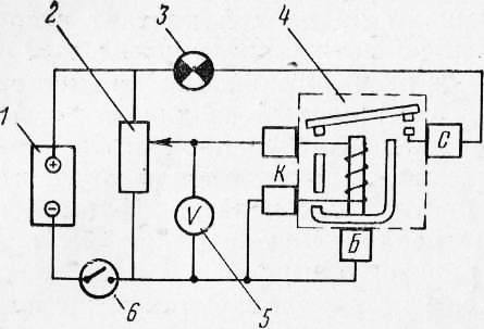
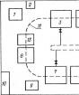
Fig. 1. Enable an additional starter relay scheme for checking and adjusting: 1 - rechargeable battery; 2 - Reostat; 3 - warning lamp; 4 - relays; 5 volt meter; 6 - Switch
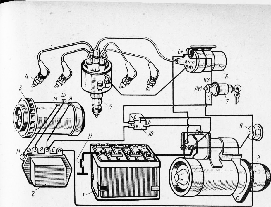
Fig. 2. Ignition system scheme: 1 - rechargeable battery; 2 - relay regulator; 3 - generator; 4 - Ignition Candle; 5 - distributor; 6 - ignition coil; 7 - ignition switch and starter; 8 - ammeter; 9 - starter; 10 - additional starter relay; 11 - Mass Switch
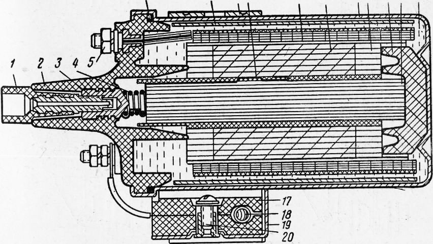
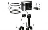
Fig. 3. Ignition Coil: 1 - High Voltage Screw; 2 - cover; 3 - high voltage terminal; 4 - Contact Spring; 5. - Low voltage terminal; 6 - Celebration gasket; 7 - metal plates for increasing the magnetic flux; 8 - fastening bracket; 9 - contact plate; 10 - primary winding; 11 - secondary winding; 12 - body; 13 - insulating gaskets; 14 - insulator; 15 - iron core; 16 - insulating mass; 17 - resistance isolator; 18 - additional resistance; 19 - plane fastening additional resistance; 20 - screw fastening resistance
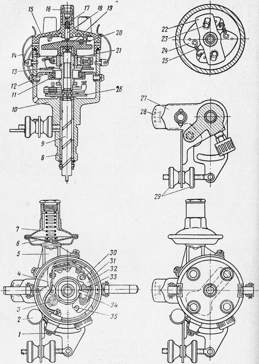
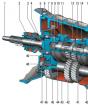
Fig. 4. Ignition distributor: 1 - Low Voltage Terminal; 2 - condenser; 3 - Filter brush; 4 - Vacuum regulator traction; 5 - vacuum regulator; "--diaphragm; 7, 17 and 25 - springs; 8 - Bearing; 9 - roller; 10 - body; 11 - ball bearing; 12 - fixed panel of the interrupter; 13 - mobile panel; 14 - spring cover holder; / 5 shn; 16 - high voltage terminal; 18 - central contact with suppressive resistance; 19 - rotor; 20 - tok offshore plate; 21 - cam; 22-plastic cam; 23 - Pottle weights; 24 - Georgics of the centrifugal regulator; 26-bills of roller; 27 and 28 plates of the Octane Corrector; 29 - nuts; 30 - locking screw; 31 - Breakfast Spring; 32 - Plate with fixed contact; 33 - contacts; 34 - armored lever; 35 - Adjusting Eccentric
The ignition coil B7-A is a transformer that converts low voltage of the primary chain into high voltage of the secondary chain required to obtain a spark between the electrodes of the candles and the ignition of the working mixture in the engine cylinders.
Attaching the ignition coil into the electrical equipment chain is shown in Fig. 2. In the primary winding of the coil, the current passes through the added resistance, which when starting the engine, the starter turns off automatically, and the current enters the primary winding, bypassing it, which is reached the amplification of the spark and facilitating the engine start.
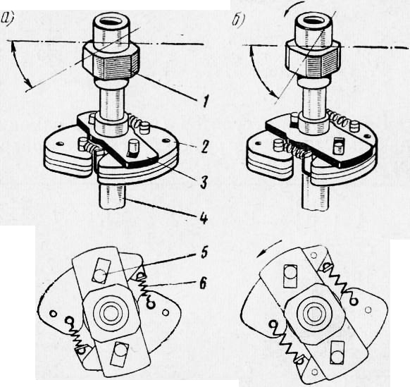
Fig. 5. The operation of the centrifugal regulator of the ignition timing: and - at idle the engine; b - at the maximum number of engine crankshaft; 1 - cam; 2 - Georgic; 3 - fist plate; 4 - roller; 5 - Pottle of Georgic, 6 - Spring
The ignition distributor of the RZ-B is mounted on the left side of the cylinder block and drives against the oil pump roller.
The ignition distributor is designed to interrupt the low voltage current in the ignition coil circuit, the high voltage current pulse distribution of the engine cylinder cylinder candles of the mixture of the mixture, depending on the number of revolutions and the engine load.
The dispenser interrupter consists of a fixed contact plate, a rolling pin lever and a four-gamped cam, which, rotating, blurs the contacts, racing the arms on the lever pad. The gap between the interrupter contacts is regulated by an eccentric. In parallel, the contacts include a CN-4 capacitor with a capacity of 0.17-0.25 microf.
The high voltage current distributor consists of a rotor and covers with electrodes that are connected by wires with a coil and candles. The rotor of the distributor during rotation transmits high voltage current pulses from the secondary winding of the ignition coil to the candles in accordance with. Procedure for the work of cylinders.
The distributor has a centrifugal and vacuum regulators that automatically change the ignition advance an octane-correlator to manually adjust the ignition angle depending on the octane number of gasoline used.
The centrifugal controller changes the ignition angle depending on the rotor of the engine (or the distributor roller).
The vacuum controller changes the ignition angle depending on the engine load (the vacuum in the inlet tube).
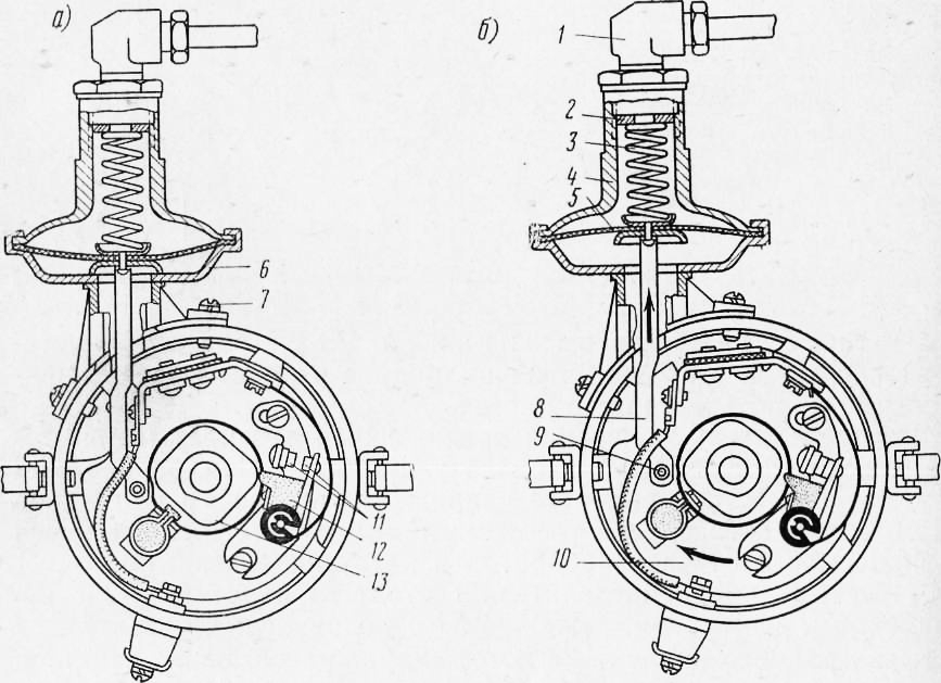
Fig. 6. The work of the vacuum regulator of the ignition advance: A - the discharge in the carburetor is small; b - discharge in the carburetor Veliko: 1 - tube fitting from the carburetor; 2 - adjusting washer; 3 -prot; 4 - lid vacuum regulator; 5 -Diaphragma; 6 - the case of the vacuum regulator; 7 - screw fastening of the regulator; S - thrust; 9 - pin; 10 - mobile panel of the interrupter; 11 - Contacts; 12 - arm arm; 13- File
The octane corrector provides a change in the ignition angle within + 10 ° at the corner of the rotation of the crankshaft.
The Ignition Candles A14U of an unbearable design have the length of the whip of the housing 14 + 0.5 mm and the metric thread M14x1.25. Clearance between candle electrodes 0.8-0.95 mm.
When adjusting the gap between the electrodes of the candles, it is necessary to bend only by the side electrode, since the insulator of the candle is bursting to the central electrode.
The ignition switch and starter of the VK21-K (Fig. 150) is used to turn the current in the primary chain of the ignition system and to turn on the starter and the radio. Installed switch on the instrument panel.
On the plastic base of the lock switch, the AM (ammeter) terminals are placed, KZ (ignition coil), st (starter), etc. (receiver). The AM terminal is under constant voltage.
When the key turns into the first right position, the AM terminal is connected to the KZ terminals, etc., ignitions are activated by the chain of control devices, a wiper, a radio receiver, a windshield blower fan, a cab fan and body heating. The radio receiver is only installed on the UAZ -452B bus.
When the key turns into the right extreme position, the AM terminal is connected to the KZ terminals and the ignition and the starter are turned on.
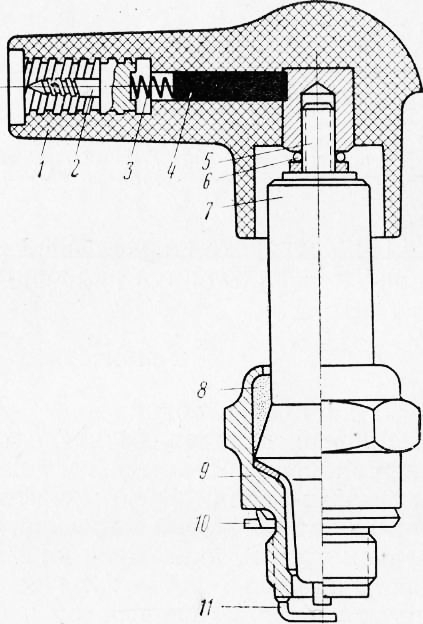
Fig. 7. Ignition Candle with Poverty Resistance:
1 - the body of the stubborn resistance; 2- contact; 3-Contact Spring; 4 - resistance; 5 - central electrode; 6 - retaining spring; 7 - insulator; 8 - seal; 9 - Candle hull; 10 - gasket; 11 - side electrode
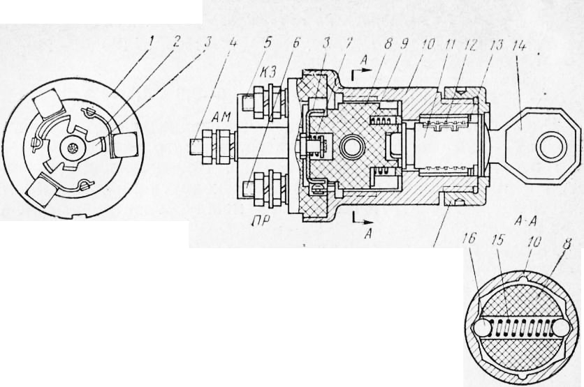
Fig. 8. ignition switch and starter: 1 - insulator with contacts; 2 - contacts; 3 - movable contact plate; 4 - Clems of AM-, 5-terminal KZ; 6 - terminal PR; 7 - Spring of the contact plate; 8 - rotor; 9 - Rotor Spring; 10 - body; 11 - locking cylinder; 12 - shut-off larvae; 13 - stop ring; 14 - key; 15 - spring; 16 - fixture balls; 17 - Nut Mounting Castle to Panel
When you turn the key to the left of the AM terminal connects to the terminal PR - the radio is turned on.
Maintenance
At T-1 it is necessary:
- check the reliability of electrical connections and fixing the ignition system devices;
- Lubricate the distributor roller by turning the cap of the cap oil. Throw one drop of oil used for the engine, on the axis of the interrupter lever, 1-2 drops on the cam flushing and 3-4 drops into the cam sleeve (after removing the rotor and filter under it). When lubricating the cam and the axis of the interrupter, it is necessary to ensure that the oil does not fall on the contacts of the interrupter.
At TU-2, in addition to the works provided for by that-1, perform the following works.
Check the condition of low and high voltage wiring and clean them from dust and dirt.
Finding the spark plugs, clean them from the car and adjust the gaps between the electrodes.
Inspect the contacts of the distributor, remove the dirt and oil from the contacts, wiping them with suede, slightly moistened in gasoline. Then wipe them with a clean dry suede or a tissue that does not leaving the fibers on the contacts.
The burnt or oxidized contacts should be carefully cleaned with a special abrasive plate included in the driver's tool kit, or a shallow glass skurt.
After stripping contacts, it is necessary to wipe the suede, slightly moistened in gasoline, and establish a normal gap between them.
Check the dipped gap between the interrupter contacts and, if it is more than 0.05 mm differ from the nominal (0.35 - 0.45 mm), adjust it.
To adjust the gap, it is necessary to turn the crankshaft of the engine with the handle so that the interrupter's cam fully open contacts. Then weaken the screw that fastening the fixed contact plate and, rotating the screwdriver head of the adjustment eccentric, shift the plate, and with it, and a fixed contact in the desired direction before getting the desired gap. After that, tighten the screw and check the gap to the dipstick again.
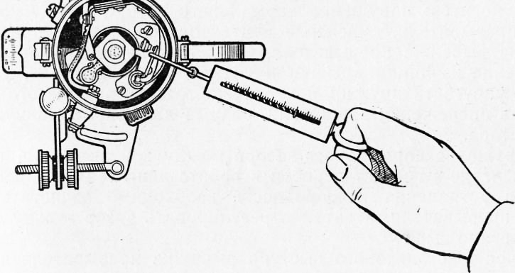
Fig. 9. Checking the interrupter spring tension
Check the lack of hot lever on the axis, for what to squeeze the lever with your finger and release it. The lever released must quickly return (under the action of the springs) and contacts must be closed with a click.
If the closure did not happen or the sluggish contact of the contacts occurred, it is necessary to eliminate the jealous and adjust the tension of the interrupter's spring within 500-700 g, removing the lever and bending the spring in one direction or another, as needed. Spring Tension The interrupter lever is checked using a spring dynamometer, as shown in Fig. nine.
Once a year, but no less often than in 25,000-300,000 miles of running and, if necessary, repair the distributor in the workshop. In this case, the distributor is disassembled, inspect all the details and, if necessary, replace.
When the dispenser is bulkhead, lubricate all the rubber parts, and the cam filhes are impregnated into the oil and pressed.
Remove the fixed panel of the interrupter, rinse the ball bearing and lay the new LZ-158 consistency grease or cyatim -201. Before panel formation, the ease of rotation of the ball bearing is checked and, if necessary, additionally turn its outer ring to the elimination of the healing.
Check the amount of carbon resistance; It must be within 6000-15 000 Ohm.
After 40,000-50,000 km of the car run in the case of a large radial backlash of the distributor roller, causing violation of spar formation, replace the roller bearings of the distributor.
The main malfunctions of the ignition system and how to eliminate them
The frequently encountered dispensers include: violation of the normal gap between the interrupter contacts, the oxidation of the contacts, the wear of the textolite protrusion lever of the interrupter, the capacitor insulation breakdown, the disorder of the insulation of the cover and rotor of the distributor, decrease the elasticity of the springs of centrifugal or vacuum control regulators, the discharge of the vacuum regulator.
Violation of a normal gap between contacts, as well as their oxidation causes interruptions in the engine operation.
To troubleshoot a malfunction, it is necessary to clean the contact of the interrupter, and then adjust the gap between them, as described above.
Wear a textolite protrusion lever of the interrupter leads to the fact that it becomes impossible to increase the gap between the contacts to normal (0.35 - 0.45 mm) of the magnitude. The lever with a worn protrusion is replaced.
When testing the capacitor isolation, the engine begins to work with interruptions, and then stops. The contacts of the interrupter are greatly overtaken. Faulty condenser replace new.
Violation of the insulation of the cover and rotor of the distributor entails the appearance of interruptions in the engine operation. Faulty lid and rotor are replaced.
A decrease in the elasticity of the centrifugal regulator springs is accompanied by the appearance of strong detonation knobs when moving the car (not only during acceleration, but also when moving at an average rate). In this case, it is necessary to increase the tension of the springs by sweeping their racks, after which check the distributor on the SPZ -6 booth.
A decrease in the elasticity of the spring regulator springs causes a change in an increase in the angle of a ignition advance at medium and large engine loads, which is accompanied by the appearance of detonation stuffs. In suspected of a decrease in the elasticity of the spring of the vacuum regulator, the distributor must be checked on the SPZ -6 stand. To increase the elasticity of the spring, install an extra washer between the spring and the fitting. After that, the vacuum regulator again check on the stand.
The violation of the tightness of the vacuum regulator usually occurs due to damage to its diaphragm. In this case, the regulator ceases to increase the ignition advance on small and medium loads, as a result of which the fuel efficiency of the car is worse. The tightness of the vacuum regulator is checked on the SPZ -6 stand. In the absence of a stand, the tightness of the vacuum regulator can be checked as follows. Remove the regulator from the distributor to bring air under the pressure of 3-4 kg / cm2 and immerse in water. At the same time, air bubbles should not be released at the site of the hull and nut connections and at the location of the lever.
The ignition coil malfunction includes insulation tributes and intersensional closures of primary and secondary windings, cracks in the lid, as well as the abnormal resistance. With breakdowns of the insulation windings, the engine stops working and it fails to start. With inter-touch closures, interruptions occur in the engine. When an additional resistance is blocked, the engine is easy to start starter, but the starter turns off the starter immediately.
Dropped additional resistance must be replaced. Faulty ignition coil replace new.
Faults of spark plugs. Any of faults of spark plugs (violation of a normal gap between the electrodes, the deposition of a large nagar layer on the housing and insulator, the appearance of cracks on the insulator) entails the occurrence of interruptions in the engine operation. The non-working candle is detected by alternately disconnecting each candle (by removing the carbetic tip) when the engine of the crankshaft operating on the lowest possible turnover of the engine. Disabling the faulty candle will not affect the uniformity of the engine. When disconnecting a good candle, the uneven operation of the engine will increase.
The faulty candle must be turned out, clean and check on the Garo model 514.
Instead of a faulty candle, you need to screw the new, checking the pre-gap between its electrodes. When installing a candle in place under its body, a copper gasket must be installed.
The gap between the electrodes of the candle is checked by round affairs available in the driver's instrument. At the same time, it is impossible to pylize with a flat probe, since it is not "" in the deepening of the sideline, the candles sampled on the process of its work.
The ignition switch is very durable and, as a rule, works without repair or replacement for several years.
Installation of ignition
Ignition of the engine must be installed with great accuracy, since even with small errors in the installation increases sharply, the fuel consumption increases, and the engine power decreases.
The order of operations when installing the ignition is next.
Remove the distributor cover and rotor and check the gap value between the interrupter contacts. If necessary, adjust the gap. Put the rotor in place.
Remove the first cylinder candle and closing the first cylinder candle with a finger, turn the engine shaft by the starting handle before the start of the outlet of the air from under the fingertip it will occur at the beginning of the compression stroke in the first cylinder.
After making sure that the compression began, carefully turn the engine shaft before the coincidence of the hole on the pulley with the pin.
Smooth setup nuts Set the Octane-corrector scale to zero division.
Loosen the screw fastening of the interrupter housing and rotate the dispenser body counterclockwise so much so that the interrupter's contacts are closed.
Take a portable lamp and using additional wires to connect one of the wires to the mass, the other to the low voltage terminal on the coil (which is attached to the wire that goes to the distributor).
Turn on the ignition and rotate the dispenser case clockwise until the light bulb flashes. Stop rotation of the distributor should be exactly at the time of flashing the light bulb. If it failed, repeat operation.
Secure the casing of the distributor with a screw, put the lid and the central wire in place.
Check the correctness of the connections of wires from the candles, starting from the first cylinder. Wires must be attached in order 1, 2, 4, 3, counting counterclockwise.
RIC. 10. Determination of the upper dead point
After each ignition installation and after adjusting the gap in the interrupter, you need to check the accuracy of setting the moment of the ignition of the combustible mixture, listening to the engine operation when the car is moving. Refiguring the ignition installation can be made by Octane-corrector, without weakening the fastening screw. To do this, it is enough to rotate the smooth setup nuts, unscrewing one and shrinking the other.
Moving the arrow to one division of the Octane-corrector scale corresponds to a change in the ignition installation by 2 °, counting on the crankshaft. When turning the dispenser's housing counterclockwise, the ignition installation will be later clockwise - earlier.
The most advantageous ignition advance will be this, in which during a sharp overclocking (full opening of the throttle) of a fully loaded car on a horizontal road with an initial speed of 30-35 km / h in direct transmission will hardly listen to the unit detonation stuffs in the engine cylinders. If there are no intense drive of the car the car, it means that ignition later; On the contrary, the appearance of a number of consecutive distinct knocks indicates too early ignition.
TO Atientary: - UAZ