Device and principle of operation of the internal combustion engine (18 photos + 4 video)
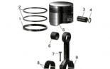
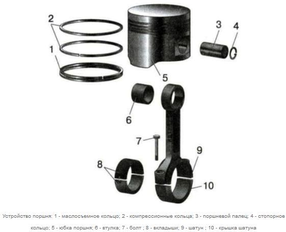
In the engine device, the piston is a key element of the workflow. The piston is made in the form of a metal hollow glass located spherical bottom (piston head) up. The guide part of the piston, otherwise called the skirt, has shallow grooves, designed to fix piston rings in them. The purpose of the piston rings is to provide, firstly, the tightness of the epipper space, where when the engine operates, the instant combustion of the gasoline-air mixture occurs and the formed expanding gas could not, encouraging the skirt, rushing under the piston. Secondly, the rings prevent oil from entering under the piston, in the epipment space. Thus, the rings in the piston perform the function of seals. The bottom (lower) piston ring is called oil-chain, and the upper (upper) - compression, that is, providing a high degree of compression of the mixture.
When the fuel-air or fuel mixture from the carburetor or the injector is inside the cylinder, it is compressed by the piston when it moves up and is ignited by an electrical discharge from the spark plug (in the dieselle there is a self-ignition of the mixture due to a sharp compression). The resulting combustion gases have a much larger volume than the original fuel mixture, and, expanding, sharply pushed the piston down. Thus, the thermal energy of fuel is converted into a reciprocating (up-down) movement of the piston in the cylinder.
Next, you need to convert this movement to the rotation of the shaft. This happens as follows: inside the piston skirt is a finger on which the top of the connecting rod is fixed, the latter is fixed on the crankshaft crank. The crankshaft is freely rotated on the support bearings, which are located in an internal combustion engine crankcase. When moving the piston, the connecting rod starts to rotate the crankshaft from which the torque is transmitted to the transmission and - further through the gear system - on the drive wheels.
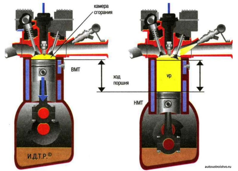
Engine specifications. Engine characteristics When moving up and down, the piston has two positions that are called dead dots. Top dead dot (NTC) is the moment of maximum head lifting and all the piston up, after which it starts to move down; Lower dead dot (NMT) is the lowest position of the piston, after which the direction of the direction changes and the piston rushes upwards. The distance between the NTT and NMT is called the piston, the volume of the top of the cylinder at the position of the piston in the VMT forms the combustion chamber, and the maximum volume of the cylinder at the position of the piston in the NMT is called full cylinder. The difference between the full volume and volume of the combustion chamber was the name of the working volume of the cylinder.
The total working volume of all cylinders of the internal combustion engine is indicated in engine specifications, it is expressed in liters, therefore, in use is referred to as the engine litter. The second most important characteristic of any internal combustion is the compression ratio (SS), defined as the private from the division of the full volume on the volume of the combustion chamber. In carburetor engines, the SS varies in the range from 6 to 14, in diesel engines - from 16 to 30. It is this indicator, along with the engine capacity, determines its power, efficiency and completeness of the combustion of the air mixture, which affects the toxicity of emissions during the operation of the DVC .
The engine power has a binary designation - in horsepower (hp) and in kilowatts (kW). To transfer units, one to another applies the coefficient of 0.735, that is, 1 hp \u003d 0.735 kW.
The operating cycle of four-stroke engine is determined by two turns of the crankshaft - on the half-turn to the tact, corresponding to the one of the piston. If the engine is single-cylinder, then in its work there is unevenness: a sharp acceleration of the piston stroke with an explosive combustion of the mixture and slowing it as it approaches NMT and then. In order to stop this unevenness, a massive disk flywheel with large inertia is installed on the shaft outside the motor body, due to which the moment of rotation of the shaft in time becomes more stable.
Principle of operation of the internal combustion engine
The modern car, the cup of everything, is driven by the internal combustion engine. There are a huge set of such engines. They differ in the volume, the number of cylinders, power, the rotational speed used by the fuel (diesel, gasoline and gas engine). But, in principle, the device of the internal combustion engine is similar.
How does the engine work and why is it called a four-stroke engine of internal combustion? About the inner combustion is understandable. Inside the engine burns fuel. And why 4 engine clutches, what is it? Indeed, there are two-stroke engines. But on cars they are extremely rare.
The four-stroke engine is called due to the fact that its work can be divided into four, equal in time, part. The piston passes four times through the cylinder - twice up and twice down. Tact begins when the piston is located at an extremely lower or upper point. In motorists-mechanics, this is called the top dead dot (NTT) and the lower dead point (NMT).
First Tact - Inlet Tact
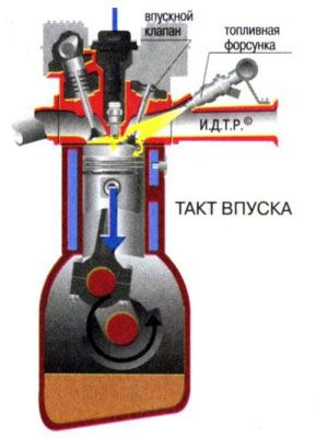
The first clock, it is intake, begins with the NTC (top dead point). Moving down, piston, sucks the fuel-air mixture into the cylinder. The work of this tact happens when the intake valve is open. By the way, there are many engines with multiple inlet valves. Their quantity, size, time spent in the open state can significantly affect the engine power. There are engines in which, depending on the pressure pedal, there is a compulsory increase in the time of finding inlet valves in the open state. This is done to increase the amount of the fuel absorbed, which, after the ignition, increases the engine power. The car, in this case, can accelerate much faster.
Second tact - compression tact
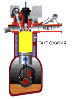
The next engine work clock is compression tact. After the piston reached the lower point, it begins to rise up, thereby squeezing the mixture, which fell into the cylinder into the intake tact. The fuel mixture is compressed to the volume of the combustion chamber. What is this camera? The free space between the upper part of the piston and the top of the cylinder when the piston is found in the upper dead point is called the combustion chamber. Valves, the engine work is completely closed in this closed. The more dense they are closed, the compression is better. It has great importance, in this case, the state of the piston, cylinder, piston rings. If there are big gaps, it will not be good compression, and accordingly, the power of such an engine will be much lower. Compression can be checked by a special device. The magnitude of the compression can be concluded about the degree of wear of the engine.
Third Tact - Working
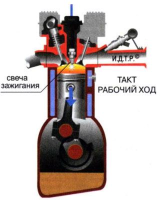
The third tact is a worker, begins with NTC. The worker it is called no coincidence. After all, it is in this tact that an action takes place that makes the car move. In this clock, the ignition system comes into operation. Why is this system so called? Yes, because it is responsible for igniting the fuel mixture, compressed in the cylinder, in the combustion chamber. It works it very simple - the system candle gives a spark. In fairness, it is worth noting that the spark is issued on the spark plug in a few degrees until the upper point is reached. These degrees, in a modern engine, are regulated by automatically "brains" of the car.
After the fuel lights up, the explosion occurs - it increases sharply in the amount, forcing the piston to move down. Valves in this engine work tact, as in the previous, are in the closed state.
Fourth Tact - issue tact
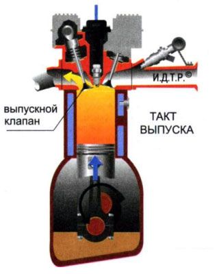
The fourth engine work tact, the last - graduation. Having reached the bottom point, after the working clock, the exhaust valve begins to open in the engine. Such valves, as well as intake, may be several. Moving up, the piston through this valve removes the spent gases from the cylinder - ventilates it. The degree of compression in cylinders depends on the clear operation of the valves, the complete removal of the exhaust gases and the required amount of the absorbed fuel and air mixture.
After the fourth tact, the first turn is coming. The process is repeated cyclically. And at the expense of which rotation takes place - the operation of the internal combustion engine is all 4 closures, what makes the piston rise and go down in compression, release and intake tacts? The fact is that not all the energy received in the working clock is sent to the movement of the car. Part of the energy goes to spout the flywheel. And he, under the influence of inertia, twists the crankshaft of the engine, moving the piston during the period of "non-working" clocks.
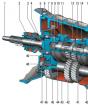
Gas distribution mechanism
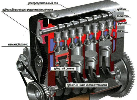
The gas distribution mechanism (timing) is intended for fuel injection and exhaust gases in internal combustion engines. The gas distribution mechanism itself is divided into the novel flap, when the camshaft is in the cylinder block, and the topless. The upperlap mechanism implies the foundation of camshaft in the head of the cylinder block (GBC). There are also alternative mechanisms for gas distribution, such as a guilty GDM system, a desmodromic system and a mechanism with variable phases.
For two-stroke engines, the gas distribution mechanism is carried out using intake and outlet windows in the cylinder. For four-stroke engines, the most common upperclamp system, about it and will be discussed below.
GRM device
In the upper part of the cylinder block is a Cylinder (cylinder head) with a camshaft, valves, pushers or rockers located on it. The camshaft drive pulley is out of the head of the cylinder block. To exclude the flow of engine oil from under the valve cover, an oil seal is installed on the camshaft neck. The valve cover itself is installed on the oil-benzo-resistant gasket. The timing belt or the chain is dressing the camshaft pulley and drives the gear of the crankshaft. For belt tension, tension rollers are used, for chains tension "shoes". Typically, the timing belt is driven by a pump of water cooling system, an intermediate shaft for the ignition system and the drive of the high pressure pump of the TNVD (for diesel versions).
On the opposite side of the camshaft by direct transmission or with a belt, a vacuum amplifier, a power steering or a car generator can be operated.
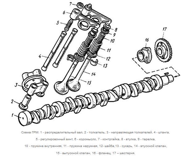
The camshaft is an axis with futs in it. The cams are located on the shaft so that in the process of rotation, in contact with the valve pushers, click on them exactly in accordance with the engine's working clocks.
There are engines and two camshafts (DOHC) and a large number of valves. As in the first case, the pulleys are powered by one timing belt and chain. Each camshaft closes one type of intake or final valves.
The valve is pressed by the rocker (early versions of engines) or pusher. Distinguish two types of pushers. The first is the pushers where the gap is regulated by calibration washers, the second - hydrotherapists. The hydrotherapist softens the blow to the valve due to the oil that is in it. Adjusting the gap between the cam and the top of the pusher is not required.
Principle of operation GRM
The entire process of gas distribution is reduced to synchronous rotation of the crankshaft and the camshaft. As well as the opening of intake and exhaust valves in a certain place of the piston position.
At the exact location of the camshaft relative to the crankshaft, installation labels are used. Before dressing the belt of the gas distribution mechanism, tags are combined and recorded. Then the belt is dressed, "exempted" pulleys, after which the belt is stretched by stretching (and) rollers.
When the valve is opened, the following happens: the camshaft "runs" on the rocker, which presses the valve, after passing the cam, the valve under the action of the spring is closed. Valves in this case are located V-figuratively.
If the engine is applied in the engine, the camshaft is directly over the pushers, when rotating, pressing its cams on them. The advantage of such timing is small noises, a small price, maintainability.
In the chain engine, the whole process of gas distribution is the same, only when assembling the mechanism, the chain is dressed on the shaft together with the pulley.
crank mechanism
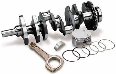
The crank-connecting mechanism (hereinafter reduced by KSM) is the engine mechanism. The main purpose of the CSM is the transformation of the reciprocating movements of the cylindrical piston into the rotational motions of the crankshaft in the internal combustion engine and, on the contrary.
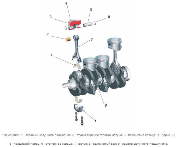
Device KSM.
Piston
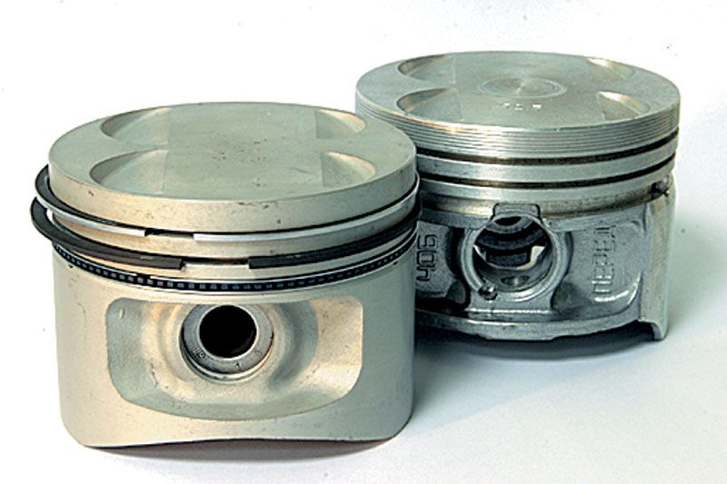
The piston has the form of a cylinder made of aluminum alloys. The main function of this part is to transform into mechanical work a change in gas pressure, or vice versa, is discharge pressure due to reciprocating movement.
The piston is folded together the bottom, head and skirt that perform completely different functions. The bottom of the piston is flat, concave or convex form contains a combustion chamber. The head has sliced \u200b\u200bgrooves, where piston rings (compression and oil perm) are placed. Compression rings exclude gases breakthrough into the engine crankcase, and the piston oil diffraction rings contribute to the removal of excess oil on the inner walls of the cylinder. There are two bins in the skirt, providing the placement of a piston pin connecting piston.
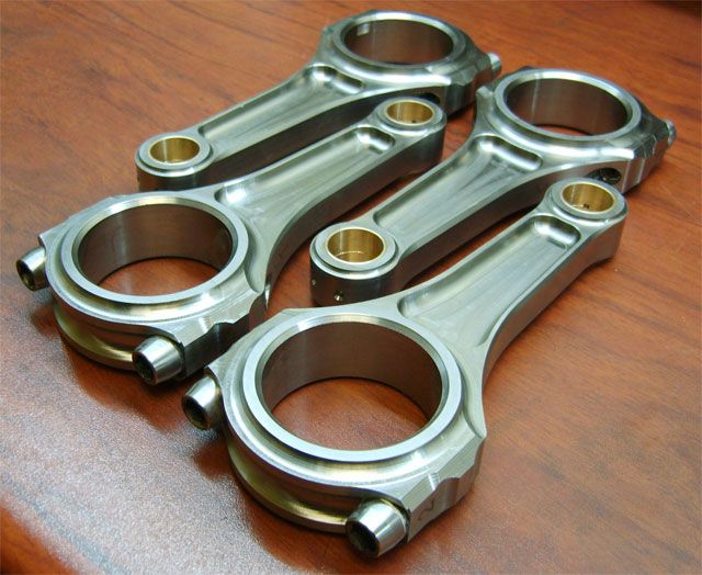
Made with stamping or forged steel (less often - titanium) rod has hinge connections. The main role of the connecting price is in the transfer of piston effort to the crankshaft. The rod design assumes the presence of the upper and lower head, as well as a rod with an inlet cross section. In the upper head and bobbies there is a rotating ("floating") piston finger, and the lower head is collapsing, allowing, thereby ensuring a close connection to the neck of the shaft. The modern technology of the controlled splitting of the lower head allows to ensure high accuracy of the connection of its parts.
The flywheel is installed at the end of the crankshaft. To date, there are wide use of two-masted flywheels, having a form of two, elastically interconnected, disks. The flywheel's geek is directly involved in starting the engine through the starter.
Cylinder Block and Head
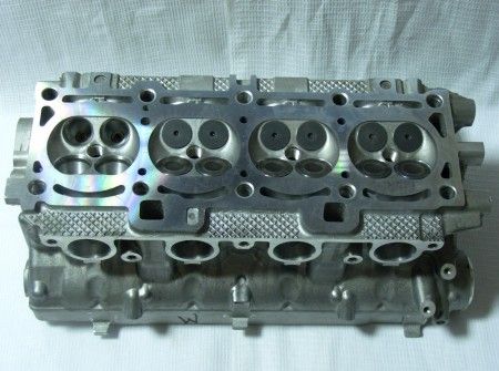
The cylinder block and the cylinder head are cast from cast iron (less often - aluminum alloys). The cooling shirts are provided in the cylinder block, beds for crankshaft and switchgear bearings, as well as the point of fixing devices and nodes. The cylinder itself performs the function of the guide for the pistons. The head of the cylinder block has a combustion chamber, intake-exhaust channels, special threaded holes for spark plugs, bushings and pressed saddles. The tightness of the connection of the cylinder block with the head is provided with a gasket. In addition, the cylinder head is closed with a stamped lid, and between them, as a rule, a laying of oil resistant rubber is installed.
In general, the piston, the cylinder sleeve and the connecting rod form a cylinder or a cylindropional group of the crank-connecting mechanism. Modern engines can have up to 16 or more cylinders.