Chevrolet Cardan
Cardan transfer of car Chevrolet Niva 2002
Design features
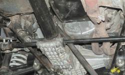
The cardan transmission is designed to transmit torque from the gearbox to the transfer box and from the transfer box to the front and rear leading shafts.
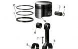
Fig. 5.7. Cardan transmission:
front cardan shaft;
intermediate cardan shaft;
transfer case;
rear cardan
The Carian Transmission of the VAZ-2123 car consists of intermediate 2 (Fig. 5.7), front 1 and rear 4 cardan shafts.
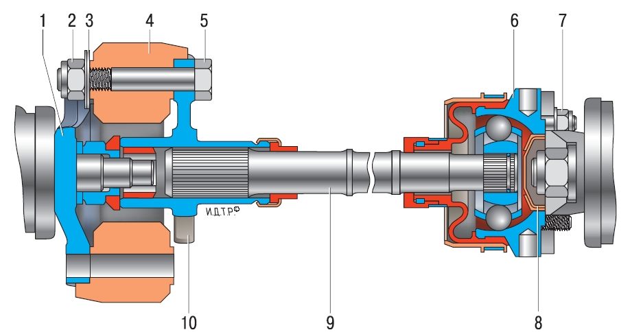
Fig. 5.8. Intermediate cardan shaft:
-
balancing washers;
elastic coupling;
flange fastening bolt;
hinge case of equal angular velocities;
-
hinge plug;
intermediate cardan shaft;
elastic coupling flange
flange of the secondary gearbox shaft;
The intermediate drive shaft is made of bar, at both ends of which slots are made. At one end of the shaft (from the gearbox), the flange 10 is set (Fig. 5.8), which is connected to the flange 1 of the secondary gearbox shaft through the elastic coupling 4. The spline connection of the flange of the elastic coupling and the shaft is sealed with a bowl.
At the other end of the shaft (from the transfer box) a hinge of equal angular velocities is installed.
The hinge housing 6 of equal angular velocities is attached to the flange of the leading shaft of the dispensing box with spills.
The design of the front and rear cardan shafts is the same. The shaft is a thin-walled steel pipe. On the one hand, the spline tip is welded to the pipe on which the sliding fork of the cardan hinge is installed. The slotted joint of the shaft and the plug is sealed with a bowl. On the other hand, the plug of the cardan hinge is welded.
Both cardan hinge are connected to the flanges, one of which (from the pipe side) is attached to the flange of the front axle gearbox, and the other to the flange of the slave shaft of the dispensing box. Each cardan hinge consists of two forks connected by the cross.
Front and rear cardan shafts with hinges of equal angular velocities can be installed on parts of the cars. Their design is similar to the design of the front wheels.
Checking the health of the cardan transmission by car
Check the cardan transmission from the bottom of the car located on the lift or viewing ditch. A neutral transmission must be enabled in the gearbox and dispensing box. Check the reliability of all the threaded connections, the state of the hinges and the rubber array of the elastic coupling of the intermediate shaft (external inspection).
1. Hold both hands behind the shaft near the checked hinge. Show every cardan shaft in directions perpendicular to its axis in short sharp movements. Tangible backlash in hinges is not allowed.
2. Repeat the check for all cardan hinges.
3. Short sharp movements turn the cardan shaft around its axis in both directions, while holding the flange flange of the cardan hinge from turning. Tangible circumferential gaps are not allowed.
4. Repeat the check on the remaining cardan hinges.
Grease cardan transmission
Slotage compounds and conversions of the cardan transmission require regular replenishment of the consistent lubrication. In the absence of lubricant, the slotted compound or the needle bearing of the crossbar is weft with the appearance of a backlash or, on the contrary, can bump. In the other case, the vibration of the cardan transmission appears.
You will need: syringe for the discharge of a grease, lubricant type Fiol-2U.
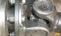
1. So there is a span-compound press oil
2. And so - the crosses of the cardan hinge.
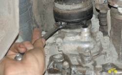
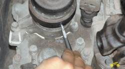
3. Using the syringe, hesitate to lubricate through the press oils of the front and rear drive shafts. Digging to reveal fresh lubricants from under seals.
Often there are problems with the access of the syringe tip to the grinding press oil, caused by the orientation of the press oil with respect to the plug of the hinge or the form / dimensions of the tip of the syringe. In the first case, the press oil can be rotated the wrench to a more convenient position. In the second case, remove the cardan shaft from the car and turn the flange plug in such a way as to provide access to press oil.
Removal and installation of an intermediate shaft
You will need: the key "at 13", "at 19" (two), a beard, a hammer.
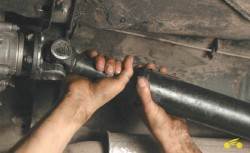
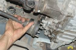
1. Unscrew the four self-locking nuts of the hinge attachment of equal angular velocities (Solus) to the flange of the leading shaft of the transfer box.
Reuse of self-locking nuts is not allowed, replace them with new!
2. With the help of a hammer and chisel, carefully mark the relative position of the casing of the shrus and the flange of the dispensing box.
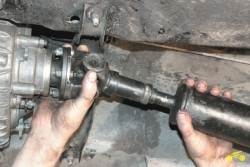
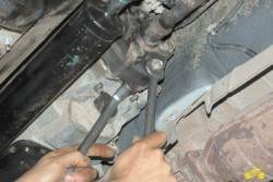
3. Loosen the nuts fastening of the power unit supports, with the help of a scrap, slide it for 1.5-2.0 cm and
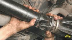
4. Display the hinge stiletto from the flange holes.
5. Unscrew the three nuts of the fastening bolts of the elastic coupling to the flange of the secondary gearbox shaft.
6. Remove the bolts from the coupling and flange holes. If the bolts come out hard, use the beard and hammer.
7. Remove the shaft.
8. Install the intermediate shaft in the reverse order.
Disassembly and assembly of an intermediate shaft
You will need: the key "at 13", "at 19" (two), a screwdriver, sliding passage, hammer.
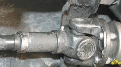
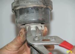
1. Clean the hinge of equal angular velocities with a metal brush.
2. Remove the hollow hinge cover clamp clamp with screwdriver and sliding passage and
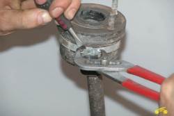
3. Slide the casing on the shaft to access the case.

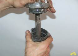
4. Remove the coat fastening clamp with sliding passage.
5. Slide the hinge case on the shaft and mark any convenient way the mutual position of the hinge and shaft.
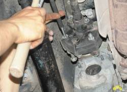
6. With the help of a hammer and a wooden spacer, escape and
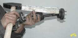
7. Remove the hinge from the shaft.
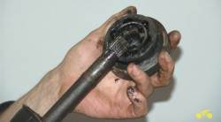
8. Remove the case and
9. Hinge casing hinge.
10. Remove the hinge check valve.
11. Unscrew the three nuts of the elastic coupling bolts. Mark the mutual location and the number of balancing washers before removing them from the coupling.
12. Remove the bolts and remove the coupling.
13. Install the details on the shaft in order of reversing, aligning the label applied before disassembling.
Removing and installing cardan transmission
You will need: key "at 13" (two), chisel, hammer.
1. Note the mutual position of the front handband flange and the flange of the front axle gearbox with a hammer and chisel.
2. Unscrew the four nuts of the boltan valve bolts to the flange of the front axle gearbox.
3. Mark the mutual position of the front handband shaft flange and dispensing flange.
4. Unscrew the four nuts of the cardan shaft mounting bolts to the dispensing flange, remove the bolts and
5. Remove the cardan shaft assembly.
6. In the same way, remove the rear drive shaft, without forgetting to note its position relative to the flanges of the dispensing box and the rear axle gearbox.
7. Install shafts by combining previously applied tags, in order to remove.
Repair of the cardan transmission
You will need: tube (gas) key, screwdriver, chisel, beard, hammer, shock puller, removal of locking rings, metal brush, penetrating lubricant (for example, WD-40).
Cardan shafts assembled off at the factory. Therefore, it is necessary to maintain when disassembling and subsequent assembly, the relative location of the parts, otherwise, when moving the car, vibrations may occur.
On the parts of the cars produced are installed front and rear cardan shafts with hinges of equal angular velocities. Disassemble and collect such shafts similarly to the appropriate operations for the front wheels (see "Disassembly and an assembly of front wheels").
1. Clean the details thoroughly.
2. Apply the label chisel, determining the mutual position of the forks of the cardan hinge.