Supply system
The power system is included in the electronic engine control system, described in detail in a separate "manual for repair and maintenance of the engine control system with distributed fuel injection."
Fuel supply system
The fuel supply system function is to supply the required amount of fuel into the engine on all operating modes. Fuel is supplied to the engine nozzles installed in the inlet tube.
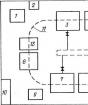
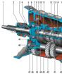
Fig. 2-62. Fuel supply system with distributed injection:
1 - fitting to control fuel pressure; 2 - ramp nozzles; 3 - fuel pressure regulator; 4 - electrical displacement; 5 - fuel filter; 6 - drain fuel line; 7 - supplying fuel line; 8 - nozzlesThe composition of the fuel supply system (Fig. 2-62) includes: electrical displacement 4, fuel filter 5, fuel lines (supplying 7 and drain 6), ramp 2 nozzles with fuel nozzles 8, fuel pressure regulator 3 and fuel pressure control unit 1.
The electric jacon pump, mounted in the fuel tank, supplies fuel through the main fuel filter and the fuel supply line on the nozzle ramp.
The fuel pressure regulator maintains a permanent pressure drop between the inlet pipe and the ramp injection line. The pressure of the fuel supplied to the nozzles is within 300 + 6 kPa with an inoperative engine. Excess fuel over the required nozzles is returned to the fuel tank along a separate plum line.
Before servicing the fuel equipment, it is necessary to reset the pressure in the fuel supply system.
When disconnecting the fuel lines, prevent the fuel strait. To do this, wind the ends of the tubes with a rag.
The procedure for dropping pressure in the fuel supply system:
1. Include neutral transmission, slow down the car in the parking brake.
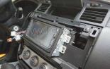
2. Disconnect the wires from the electrical space (see Fig. 2-63), to do this, tilt the rear seat cushion forward and remove the hitch of the electrical space.
3. Run the engine and give it to work at idle to stop due to fuel generation.
4. Turn on the starter for 3 seconds for pressure booming in pipelines. After that, it is safe to work with the fuel supply system.
5. After pushing pressure and completion of work, connect the wires to the electrical space.
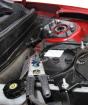
Fig. 2-63. The location of the electrobenzonasosos
Electrical displacement.
The system uses a turbine-type electrical displacement. The pump provides fuel supply from the fuel tank through the trunk fuel filter on the nozzles ramp. Excess fuel returns to the benzobac along a separate plum line.The electrical displacement is included with the controller through the relay. When installing the ignition key to the ignition position or starter after staying for more than 15 seconds in the off position, the controller is powered by a relay for 3 seconds to create the necessary fuel pressure in the nozzles ramp.
If the engine scroll during this time does not start, the controller turns off the relay and waits for the scroll start. After its start, the controller again includes relays.
Fuel filter 1 (Fig. 2-64) is mounted under the bottom of the body near the fuel tank 2. The filter is built into the feeding line between the electrical space and the fuel ramp.
The filter has a steel housing with threaded fittings from both ends. The filter element is made of paper and is designed to capture particles that can lead to a violation of the operation of the injection system.
![]()
Fig. 2-64. Fuel filter location:
1 - fuel filter; 2 - Fuel tankFuel filter removal:
1. Reset the pressure in the fuel supply system (see above).
2. Remove the nuts fastening the fuel tubes to the filter. Do not allow the loss of sealing rings installed between the filter and tips of the tubes.
ATTENTION. Be sure to use the second key from the fuel filter when turning the fastening nuts.
3. Remove the filter fastening clamp.
Installing the fuel filter
Check sealing rings for cuts, care or scuffs. Replace the rings if necessary.
1. Install the filter so that the arrow on its housing corresponds to the fuel feed direction, and secure the filter with a clamp.
2. Attach fuel tubes to the filter, tightening the mounting nuts of 20-34 N · m.
ATTENTION. Be sure to use the second key from the fuel filter when tightening fastening nuts.
3. Using the supply of voltage +12 to the PGC pin of the diagnostic pads to turn on the electrical displacement and verify the absence of fuel leaks.
Removing the ramp of the nozzles
When removing the ramp, be careful not to damage the contacts of the connectors and the nozzles sprayers.
Do not allow dirt and extraneous materials to open pipelines and channels. During maintenance to close the fitting and holes with plugs.
Before removing the nozzle ramp can be cleaned with a sprayed engine cleaning agent. Do not dip the ramp in the solvent for flushing.
2. Turn off the ignition.
4. Disconnect the throttle drive from the throttle and receiver.
5. Disconnect the inlet pipe hose from the throttle.
6. Unscrew the nuts of fastening the throttle pipe to the receiver and without disconnecting the coolant hoses, remove the throttle nozzle from the receiver.
7. Remove the supply tubes and drain fuel by disconnecting them from the nozzle ramp, pressure regulator and from the bracket on the cylinder head.
ATTENTION. Be sure to use the second key on the side of the fuel supply fitting fuel ramp when turning out the fuel tube's precipitated nut.
8. Disconnect the vacuum hose from the pressure regulator.
9. Remove the auto mount nuts and remove it from the inlet tube.
10. Remove the nozzle wiring harness, disconnecting it from the injection system harness and nozzles.
11. Unscrew the fastening bolts of the nozzles and remove it.
ATTENTION. If the nozzle separated from the ramp and remained in the inlet tube, it is necessary to replace both sealing rings and the nozzle lock.
Installation ramp nozzles:
Replace and lubricate new sealing rings injectors with engine oil, install the fuel rail assembly on the cylinder head and secure bolts, tightening them with a point of 9-13 N · m.2. Attach the wiring harness nozzles.
3. Install receiver.
4. Install the fuel tubes by tightening the fastening nuts to the ramp and the pressure regulator with a torque of 20-34 N · m.
ATTENTION. Check the fuel tubing sealing rings for cuts, care or scuffs. Replace if necessary.
Be sure to use the second key on the side of the ramp fitting when tightening the fuel tube nut.
5. Install the pressure regulator vacuum hose.
6. Install the throttle nozzle on the receiver and secure it with nuts.
7. Attach the hose of the intake pipe to the throttle pipe.
8. Install the throttle drive and check its operation.
9. Attach the wire to the terminal "minus" battery.
10. Using the voltage supply +12 to the PGC pin of the diagnostic pads to turn on the electrical displacement and verify the absence of fuel leaks.
Fuel injectors
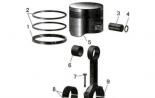
The nozzle (Fig.2-65) of the distributed injection system is an electromagnetic device that doses the fuel supply under pressure to the engine inlet tube.
Fig. 2-65. Installation of fuel injectors:
1 - inlet valve; 2 - nozzle; 3 - plug connector; 4 - retainer; 5 - ramp nozzles; 6 - sealing rings; 7 - inlet tubeThe nozzles are fixed on the ramp using spring locks 4. The upper and lower ends of the nozzles are sealed with sealing rings 6, which should always be replaced with new ones when removing and installing nozzles.
A nozzle, which occurred valve grab in a partially open state, causes pressure loss after the engine is turned off, so there will be an increase in the scroll time on some engines.
In addition, the injector with the closed valve can cause a caliling ignition, t.
to. Some fuel will fall into the engine after it is muted.Removal of nozzles:
1. Remove the nozzles ramp (see above "Removing the nozzle ramp").
2. Remove the nozzle lock.
3. Remove the nozzle.
4. Cut sealing rings from both ends of the nozzle and throw it away.
ATTENTION. When removing the nozzles, care caution so as not to damage the plugs of the connector and sprayers. The nozzle is not disassembled.
No dive into the washing fluids, t.
to. nozzles contain electrical nodes.Motor oil is not allowed inside the nozzle.
Installing nozzles:
1. Lubricate new sealing rings with clean engine oil and install on the nozzle.
2. Install a new nozzle lock (if necessary).
3. Insert the nozzle into the ramp socket so that the connector is turned up. Insert the nozzle into the socket before the latch is engaged with the groove on the ramp.
4. Install the nozzle ramp assembly (see above "Installing the nozzle ramp").
FUEL PRESSURE CONTROL
The regulator function is to maintain a permanent pressure drop on the nozzles. The pressure regulator compensates for the change in the load of the engine, increasing the fuel pressure while increasing the pressure in the inlet tube (with an increase in the opening of the throttle).
With a decrease in pressure in the inlet tube (reducing the opening of the throttle), the regulator reduces fuel pressure. At the same time, the valve of the regulator opens and excess fuel on the drain highway merges back to the fuel tank.
When the ignition is turned on, a non-working engine and an electrical displacement, the fuel pressure in the nozzle ramp is 300 + 6 kPa.
The reduced fuel pressure leads to a violation of the engine operation.
Removing pressure regulator:
1. Reset the pressure in the fuel supply system.
Turn off the ignition.3. Disconnect the wire from the "minus" terminal of the battery.
4. Disconnect the vacuum hose from the pressure regulator.
5. Disconnect the fuel plum tube from the pressure regulator.
6. Remove the pressure regulator from the nozzle ramp, unscrewing the fastening bolts and turning the left-right regulator to the restraint.
Installation of pressure regulator
1. Install the pressure regulator on the ramp of nozzles and fasten the bolts, tightening them with the moment 8-11 N · m, pre-lubricating sealant.
2. Install the fuel drain tube, tightening the threaded compounds of 20-34 N · m.
3. Install a vacuum hose.
4. Attach the wire to the terminal "minus" battery.
5. Using the voltage supply +12 to the PGC pin of the diagnostic pads to turn on the electrical displacement and make sure that the fuel leaks are missing.