Generator from a stepper motor from the printer. My homemade wind generator on the stepping motor
Stepper engine This is not only a motor drivening all sorts of devices (printer, scanner, etc.), but also a good generator! The main advantage of such a generator is that he does not need large revs. In other words, even with small revolutions, the stepper engine produces quite a lot of energy. That is, the usual cycling generator requires initial speeds until the lantern starts shining with bright light. This deficiency disappears when using a stepper motor.
In turn, the stepping motor has a number of shortcomings. The main of them is a great magnetic sticking.
Anyway. First, we need to find a stepper engine. There is a rule: the engine is more - the better.
Let's start with the largest. I walked it out of the plotter for printing, this is such a big printer. The engine looks pretty big.
Before showing you a stabilization and nutrition scheme, I want to show you the attachment method to your cycle.

Here is another option with a smaller engine.


I think each of you when building will choose the most suitable option for him.
Well, now the time has come to talk about lanterns and nutrition chains. Naturally all lamps - LED.
The straightening scheme is normal: a block of rectifier diodes, a pair of large capacitance capacitors and a voltage stabilizer.
Usually, from the stepper motor, there are 4 wires corresponding to two coils. Therefore, in the figure, two rectifier blocks.
Creating a wind generator It does not necessarily mean the manufacture of a large and powerful complex capable of providing electricity whole home or consumer group. It can be made, which is, in fact, a valid model of a serious installation. The purpose of such an event may be:
- Acquaintance with the basics of wind power.
- Joint learning classes with children.
- An experimental sample that anticipates the construction of a large installation.
The creation of such a windmill will not require the use of a large number of materials or tools, you can do with appliant means. It is not necessary to count on the production of serious energy volumes, but for the power of a small lamp on the LEDs can be enough. The main problem that exists when creating is a generator. It is difficult to create independently, since the size of the device is small. The easiest to use to use it in the generator mode.
Homemade stepper-based windmill
Most often, when production of low-power wind generators Use stepper electric motors. The feature of their design is in the presence of several windings. Usually, depending on the size and destination, engines are made with 2, 4 or 8 windings (phases). When the voltage is applied to them, the shaft turns accordingly to a certain angle (step).
The advantage of stepper motors is the ability to produce quite high current at low speeds. The generator from the stepper motor can be installed an impeller without any intermediate devices - gear, gearboxes, etc. Electricity generation will be made with the same efficiency as on devices of another design with the use of increases.
The difference in speeds is very significant - to obtain the same result, for example, on the collector engine, the speed of rotation is required 10 or 15 times more.
It is believed that with a generator from a stepper motor, you can charge batteries or batteries mobile phonesBut in practice, positive results are celebrated extremely rarely. Basically, power supplies are obtained for small lamps.
The disadvantages of stepper motors include a significant effort required to start rotation. This circumstance reduces the sensitivity of the whole that can be somewhat adjusted by increasing the area and scope of the blades.
You can find such engines in old drives for flexible media, in scanners or printers. Alternatively, you can purchase new engineif in stock the desired device It will not be. For a larger effect, you should choose larger engines, they are able to produce quite a lot of tension so that it can be somehow used.
Wind generator from the details from the printer
One of suitable options - Using a stepper motor from the printer. It can be removed from the failed old device, in each printer at least two such engines. Alternatively, you can buy a new, non-operating. It is able to produce power about 3 watts even at low wind, typical of most regions of Russia. The voltage that can be achieved is 12 or more in, which allows you to consider the device as the ability to charge batteries.
Stepper engine Gives alternating voltage. For a user, you must first straighten it. It will be necessary to create a diode rectifier, for which 2 diode will be required for each coil. You can directly connect the LED to the conclusions of the coil, with sufficient speed of rotation, this is enough.
The rooter impeller is easiest to install directly on the motor shaft. To do this, it is necessary to make a central part capable of close to the shaft. Imaging impeller fixation is needed to drill the hole and cut the threads in it. Subsequently, a locking screw is screwed into it.
For the manufacture of blades, polypropylene sewage pipes are usually used or other suitable materials. The main condition is low weight and sufficient strength, since the blades are sometimes gaining quite a decent speed. The use of unreliable materials can create an undesirable situation when the impeller falls apart on the go.
Blades
Typically produced 2 blades, but you can make more. It must be remembered that the large area of \u200b\u200bthe blades increases the windmill cyserBut in parallel with this, the front load on the impeller transmitted by the engine shaft increases. The manufacture of small blades is also not recommended, as they will not be able to overcome the shaft sticking at the start of rotation.
For the possibility of rotating the windmill around the vertical axis, a special node must be made. The complexity in this is the need to ensure the fixability of the cable that comes from the generator. Since the device has, rather, decorative purpose, usually fit the question easier - the consumer is installed directly on the generator body, eliminating the presence of a long cable. Otherwise, you will have to mount the system like a brush manifold, which is irrational and requires a large amount of time.
Mast
The collected windmill must be installed on a height of at least 3 meters. Wind streams near the surface of the Earth have an unstable direction caused by turbulence. Lifting to some height will help get more uniform streams. For independent installation On the wind along the rotation axis, the tail stabilizer playing the role of the weather. It is made from any piece of plastic, aluminum plate or other progenic material.
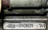
I was lying around the stepper engine and, I decided to try it to use it as a generator. The engine was removed from the old matrix printer, the inscriptions on it are as follows: EPM-142 EPM-4260 7410. The engine caught a unipolar, which means that this engine has 2 windings with a tap from the middle, the winding resistance was 2x6.
For the test you need another engine to promote stepper. The design and fastening of the engines is shown in the drawings below:
I was lost from the engine from the engine, so I put on the pasta ...

Smoothly start the engine so that the gum does not fly. I must say that high revolutions She still flies, on this voltage above 6 volts did not raise.

We connect a voltmeter and start testing, for starters, measure the voltage.

Exhibit voltage on bp about 6 volts, and the engine consumes 0.2 amps, for comparison idling The engine has driven 0.09A.

I think nothing to explain is not necessary and everything is clear in the photo below. The voltage was 16 volts, the turnovers of the spinning engines are not big, I think that it is more stronger to unwind, it is possible and all 20 volts squeeze ...

We connect through the diode bridge (and the condenser is not forgetting, otherwise you can burn the LEDs) with supermarital LEDs, the power of which is 0.5 watts.

Set the voltage slightly less than 5 volts, so that the stepper motor after the bridge gives up about 12 volts.

Shines! The voltage at the same time from 12 volts was caught up to 8 and the engine began to spin slightly slower. The current of the KZ without the LED tape was 0.08A - I remind you that the spinning engine worked not on full power, And do not forget about the second winding of the stepper engine, it is impossible to parallel them, but I did not want to collect the scheme.

I think, from a stepper motor, you can make a good generator, attach it to a bike, or make a wind generator based on it.
Tigrezno.
The following instruction is provided with which you can "recycle" an old scanner into an impressive generator of electricity.
We will need:
- Old scanner;
- Straightening diodes (in the project 8 diodes 1N4007);
- Condenser 1000 μF;
- PVC pipe;
- Plastic parts (see below);
- Aluminum plates (you can use any other).
In addition to the fluorescent pipe and electronic components, in the scanner there is a stepper engine, it is he will need it. The photo shows a four-phase stepper engine.

Note 3. FREE software was used to develop a scheme http://qucs.sourceforge.net/.


We collect blades. In details .


Unfortunately, the scheme of the device is not, however, it is not so difficult to assemble a similar photo.

The end! Now it remains to wait for a windy day and test the device, as you can see in the photo - the device consistently generates a voltage of 4.95 V. Now you can charge a MP3 player or phone for free!
- Here. Excellent man said. The question is not in the "Fairy CPD": the energy is still a gratitude. The planet will not appease from such Kulibins. The question in the labor costs and the value of the entire applied. The question is very controversial: the vertical of the terrible dimensions, or the horizontal, but turning. This is the topic for disputes (and better if there are someone to extinguish with practical experience and shares).
- hello everybody. I have a little more complicated. Lighting the yard with LED lanterns (5pcs. 7 LEDs). The battery costs 7.2 Volta 700 mA. Collected according to the voltage doubling scheme. :).
- the wind is medium, I don't know how to measure ... I stopped a little, and it is worthless.
- but the "head". (removed the multiplier, sticking up a lot with him with him and the difference is minimal, and not noise). I have a vertical in general, it is not offended and shines for 1.5 years without a battery (also shd).
- mBA1 rights, and at vertical more than 200 rpm under a big doubt.
- The blades seem to me are big for such a engine. To fit the size of the power, you look at the very correct windmill. Did not measure the parameters?
- The blades made the burden and rooted, the diameter of about 1.1m, the turns rose, and they are spinning when the wind is inappropriate. Fans are already 6 :). Here is a video - http://depositfiles.com/files/18bs0ha7b
- the parameters are already not remembered, with the middle wind about 8 volts, Ma -khz, now you want to climb there, and the head is scored, neodymium magnets waiting (24pcs), the other day will come :), I will make a generator :).
- If you need a stepper motor, then not from the scanner, but from the printer, in the matrix, there are two of them, even with the service with a quick movement of the head of the light diodes started glowing. I think to start not with a serious craft, but to start the engine from the Zhigulovsky stove, or the motor from the glass cleaner is lying in the garage.
- There are collector engines (for example, dp ..., dpm ...) with a centrifugal speed limiter. Maybe there are ideas how to adapt to the feedback in the generator? I somehow do not understand ...
- And ISSD3-shd5 someone can mutil?
- Or with motors from avio models-sizes Little power big?
- http://vkontakte.ru/club11998700 - There are photos and video shd, neodymium, links ....
- And what are the parameters from the engines? Volt on the coil? Amperezh? How many coils (conclusions?) And what is the degree of rotation?
- it is desirable to selectively pick up - less winding resistance, larger working voltage, then the step of a funeral pulse will give :)
- If less resistance with larger tension means, the power is greater. So you can choose in size :)
- http://www.youtube.com/watch?v\u003d7wgs4kxobi0&feature\u003dchannel_video_title
- This is my video.
- Who knows, any shd can be used as a generator? If you buy more powerful than in the printer.
- Use a powerful SD as a generator is difficult. Cause at a large point of touch.
In this article, I will describe the entire cycle of the stepping electromotor driver for experiments. This is not a final option, it is designed to manage one electromotor and is necessary only for research, the scheme of the end-driver stepper driver will be presented in a separate article.
In order to make a stepping motor controller, it is necessary to understand the principle of operation of the stepping electrical machines themselves and what they differ from other types of electric motors. And the varieties of electrical machines there are a huge set: DC, AC. AC electric motors are divided into simultaneous and asynchronous. I will not describe each type of electric motors, I will not become so, as it goes beyond the scope of this article, I will only say that each type of engine has its advantages and disadvantages. What is a stepper electric motor and how to manage?
The stepping motor is a synchronous brushless motor with several windings (usually with four), in which the current supplied to one of the stator windings causes the rotor fixation. Sequential activation of the engine windings causes discrete angular movements (steps) of the rotor. The conceptual electrical circuit of a stepper motor gives an idea of \u200b\u200bits device.
And in this picture shows the truth table and the step of the step in full-ha-step mode. There are also other modes of operation of stepper motors (semi-adequate, microshop, etc.)
How to rotate the rotor in the other direction? Yes, it is very simple, you need to change the sequence of signals with ABCD to DCBA.
And how to rotate the rotor to a specific specified angle, for example 30 degrees? Each model of the stepping electric motor has such a parameter as the number of steps. At the heads that I pulled out this parameter 200 and 52 from the matrix printers, i.e. To make a complete turn of 360 degrees in one engines, you need to pass 200 steps and to another 52. It turns out to rotate the rotor at an angle of 30 degrees, you need to go through:
-In the first case 30: (360: 200) \u003d 16,666 ... (steps) can be rounded up to 17 steps;
- In the second case, 30: (360: 52) \u003d 4.33 ... (step), you can round up to 4 steps.
As you can see there is a fairly big error, we can conclude that the more steps at the motor, the smaller the error. The error can be reduced if you use a semi-step or micro-drive mode of operation or mechanically - use a lower reducer in this case, the speed of movement suffers.
How to control the speed of rotation of the rotor? It is enough to change the duration of the pulses of the ABCD submitted to the inputs, the longer the pulses along the time axis, the less speed Rotation of the rotor.
I suppose this information will be enough to have a theoretical idea of \u200b\u200bthe operation of stepper electric motors, all other knowledge can be obtained experimenting.
And so let's go to the circuitry. How to work with a stepper engine, we dealt with, it remains to connect it to Arduino and write a control program. Unfortunately, directly connect the winding of the motor to the outputs of our microcontroller is impossible for one simple reason - the lack of power. Any electromotor passes through its windings a sufficiently high current, and the load can be connected to the microcontroller.40 MA (ARDUINOMEGA 2560 parameters). What to do if there is a need to control the load for example 10a and even voltage 220V? This problem can be solved if between the microcontroller and the stepping motor integrate the power electrical circuit, Then it can be controlled by a three-phase electric motor that opens a multiple hatch into a rocket mine :-). In our case, the hatch does not need to open the rocket mine, we just need to make it work stepper motor And in this we will help the driver of the stepping motor. Of course, you can buy ready-made solutions, there are a lot on the market, but I will do my own driver. To do this, I will need force key key field transistors MOSFET, as I said these transistors are ideal for interfacing Arduino with any loads.
Figure below shows the electric schematic scheme stepping motor controller.
I applied as strength keys The IRF634B transistors are the maximum voltage source-flow 250V, flow current 8,1A, this is more than enough for my case. With the scheme, we will less understand the printed circuit board. Painted in the built-in Paint editor, I will say this is not the best idea, next time I will use some specialized and simple editor of printed circuit boards. Below is a drawing of a finished circuit board.
Next, this image in the mirror reflection is printed on paper using a laser printer. The brightness of the print is best to make the maximum, and the paper needs to use not the usual office and glossy, conventional glossy magazines are suitable. We take a leaf and typing over an existing image. Next, the resulting picture apply to a predetermined piece of foil fiberglass and a good stroke in the iron for 20 minutes. Iron need to heat up to maximum temperature.
How to prepare Textolol? Firstly, it needs to be cut into the size of the image of the printed circuit board (with the help of metal scissors or hacking for metal), secondly sanding the edges of small emery paper so that there are no burrs. It is also necessary to walk the sandpaper on the surface of the foil, remove oxides, the foil will acquire a smooth reddish tint. Next, the surface treated with emery paper should be wiped with a cottage moistened to the solvent (use 646 solvent it also stinks).
After warming up the iron, the toner from paper is baked on the surface of the foil glassstolite as an image of contact tracks. After this operation, the paper fee must be cooled to room temperature and put in the bath with water for about 30 minutes. During this time, the paper will rays and it needs to be carefully rolling with the pillows of the fingers from the surface of the textolite. On the surface will remain smooth black traces in the form of contact tracks. If you did not manage to transfer the image from paper and you have flaws, then the toner should be flushed from the surface of the textolite with a solvent and repeat everything again. I did everything from the first time.
After receiving the high-quality image of the tracks, it is necessary to raise the extra copper, for this we will need the etching solution that we will prepare themselves. Previously, for etching printed circuit boards, I used a copper vigorous and a conventional cook salt in a ratio of 0.5 liters of hot water 2 tablespoons with a slide of copper mood and a cook salt. All this was carefully stirred in water and the solution is ready. But this time I tried a different recipe, very cheap and affordable.
Recommended method for the preparation of the pools:
In 100 ml of pharmacy, 3% of hydrogen peroxide dissolves 30 g of citric acid and 2 teaspoons of a cook salt. This solution should be enough to etch the area of \u200b\u200b100 cm2. Salt in the preparation of the solution can not be sorry. Since it plays the role of the catalyst and in the etching process is practically not consumed.
After the preparation of the solution, the printed circuit board must be omitted into the container with the solution and observe the process of etching, the main thing is not to reveal. The solution will eat uncovered toner surface of copper as soon as this will take place to get and rinsed with cold water, then it needs to dry and remove the toner from the surface of the tracks using the rolling and solvent. If your board provides holes for fastening radio components or fasteners, it's time to drill them. I lowered this operation due to the fact that it is just a stepper motor dye intended for the development of new technologies for me.
We proceed to the luggage of the tracks. It must be done to make it easier for soldering. I used to be thin with solder and rosin, but I will say this "dirty" way. From rosin a lot of smoke and slag on the board that will need to wash off the solvent. I applied another method, the lentation of glycerin. Glycerin is sold in pharmacies and worth a penny. The surface of the board must be wiped with a mock-moistened in glycerin and apply fine smears with a solder. The surface of the tracks is covered with a thin layer of solder and remains clean, excess glycerin can be removed with a rut or rinse in water with soap. Unfortunately, I do not have a photo of the result obtained, after the meadow, but the resulting quality is impressive.
Next, you need to solder all radio components on a fee, I used tweezers for soldering SMD components. Glycerin used the flux. It turned out very carefully.
The result is obvious. Of course, after the manufacture, the board looked better, in the photo it is already after numerous experiments (for this it was created).

So our stepping motor driver is ready! Now go to the most interesting to practical experiments. We solder all the wires connect the power supply and write the control program for Arduino.
Arduino development environment is rich in various libraries, to work with a stepper engine there is a special STEPPER.H library, we will use it. How to enjoy the Arduino development environment and describe the syntax of the programming language I will not look at this information at http://www.arduino.cc/, there is also a description of all libraries with examples including the description of Stepper.h.

Listing programs:
/*
* Test program for the headship
*/
#Include.
#Define Steps 200.
STEPPER STEPPER (STES, 31, 33, 35, 37);
void setup ()
{
stepper.setspeed (50);
}
void loop ()
{
STEPPER.Step (200);
Delay (1000);
}
This control program makes one full turn of the stepping motor shaft, after a break lasting in one second, repeated to infinity. It is possible to experiment with the speed of rotation, the direction of rotation as well as corners of turns.