Steam machines with swing cylinders. Four-stroke internal combustion engine with swing cylinder
This will not hear such a competition today. Meanwhile, in the 20s of the 20s, many models used on ship, auto and even aircraft models of the steam engine. Steam machine with a swing cylinder was most popular. It is easy to manufacture- However, we will provide the word to the author - modelist Alexander Nikolayevich Ilyina: at the request of the editors, he made and experienced a ship with such an engine
Reliability and safety are the main criteria that I was guided by choosing the type of steam machine. A steam engine with a swing cylinder, as the tests have shown, with the correct, neat production of the model, withstand even twice overloads.
But no wonder I emphasized accuracy - in it the key to success. Try to accurately fulfill all our recommendations.
Now let's talk about the steam engine itself. Figures I and II show the principle of its action and device.

On the bed 11, the cylinder (parts 1, 2 and 13) with a spool plate 8 are highly strengthened. For the input and exit of steam in the cylinder and the spool plate, a hole was drilled 3. In addition, another spoke plate was installed on the bed 4. Two are drilled in it. holes. In the process of operation of the steam engine, when the cylinder hole is aligned with the right opening of the spool plate 4, the pair enters the cylinder (see Fig. I, phase a). Expanding steam pushes the piston 13 down - to the so-called lower dead point (phase b). Thanks to the flywheel 9, the piston movement at this point will not stop dried by inertia, it rises up, pushing the spent steam. As soon as the opening of the cylinder coincides with the left hole of the plate 4, the pairs will go out into the atmosphere (phase B).
Slot plates, as you understand, should be tightly adjacent to each other, otherwise steam will penetrate the gap and the engine efficiency will noticeably decrease. Therefore, on the axis 7, the spring is installed, pressing the plate 4 to plate 8. In addition to the main function, this node also performs the role of a safety valve. When the pressure in the boiler for any reason increases, the spring will be squealing, the plates will disperse and excess the pair will come out. Therefore, the spring is tightened with nut so that the engine shaft can make several inertia revolutions. Check it out by turning it with your hand.
Couples in the car enters through the tube 5. One end is connected to the inlet hole on the spool plate 4, on the other, the hose 6, connected to the steam boiler. For our engine, any rubber hose is suitable, not containing dense or wire hardening elements. But it is best from the car benzing.
The hose on the steam line is not fixed. This is also a security measure. With increasing pressure, the pair hose is torn off the tube, and the pressure in the boiler will instantly fall.
The main working body of the machine is a cylinder 1. From above, it is covered with a tin walker 2, the bottom is closed with a piston 13.
In the piston of the rod of the knitting needles with a washer at the end. Through her hole passes the finger of crank 14, soldered to the shaft 10 propeller, also made of the knitting needles. A flywheel 9 was installed on the shaft. The steam machine shaft rotates in the sliding bearing 12, which is soldered into the bed.
For the cylinder, select the brass tube with a diameter of 12-16 mm. The inner surface should be carefully polished. It is advisable to do it on a lathe with a rod with a gauze tampon, grated paste gay or any other for polishing metals. As a result of processing, the diameter of the tube at the ends may be greater than in the middle. Therefore, only the middle part is used for the cylinder, accordingly increasing the length of the workpiece.
Sold to the finished cylinder, roll the tin cover, rinse the assembled Detail of kerosene and take on the piston. It consists of a piston itself, rod and washers.
Piston is desirable to make bronze or cast iron. Crush the workpiece to the latch to such a diameter so that it is tightly entering the cylinder. Sample without removing from the cartridge, and then drill the hole for the rod. Now cut the workpiece of the desired length and blow into it the rod. Sky the puck to the stock.
If the piston diameter turned out to be greater than necessary, it is rated with a file with a shallow notch and sandpaper, and then polished. It is done on the lathe with a bike strip and polishing paste.
Slot plates are preferably cut from brass with a thickness of 2-3 mm. For a more dense adjacent to the cylinder in the spool plate 8, make a recess. And then drill a hole under the axis 7 - screw with a diameter of 3 mm with a secret head (the figure shows the markup of the plate).
On the spool plate 4 with the help of a circulation and a core, take a place for inlet and outlet. Drill them and proceed to grinding both plates with emery paper. Then they are also polished.
The spool plate 8 needs to be soldered to the cylinder. First, insert the axis into it, tie a thin wire to the cylinder, lubricate the soldering places to the flux, sort them with slices of solder and warm on the gas burner. Solder spread over the surface, lubricated flux, and grab the part. If the cylinder cover is dropped during heating, it does not matter - it is easy to solder again.
In the cylinder you need to drill holes for steam. Conductor for them can serve as a steam distribution hole 3 in the plate V.
The assembled node is attached on the bed 11, bent out of the tin. Making it, try to accurately withstand the distance between the axis 7 and the axis of the bearing 12.
To the finished bed, solder the spool plate 4, the tube 5 of the steam pipeline 6, the bearing 12. The hole for the shaft 10 is drilled along the place, and the distance between the details of the bed is selected depending on the size of the flywheel 9.
The flywheel can serve as any steel or bronze, detail, the dimensions of which are not less than those specified in our figure. Bearing 12 best to pull out bronze.
Now let's talk about the manufacture of a steam boiler (Fig. III).

Print 1 (side surface) boiler Bend from tin. In the ending part of it, we have two slightly concave tin rigs 2. The shelter is manufactured as follows. Stripes of tin from a canning can be 80 mm wide and stretching about 200 mm long, stretch around a thick rod - the blank will take the form of the correct ring. Cut out the lane from it the desired length and smear the cylinder with a diameter of 40 mm. Rounds 2 are made on the form of the already soldered boiler. The usual flat donyshko withstand the pressure of the couple will not be able. Therefore, give the workpiece a spherical shape. This is done with light blows hammer with a convex brisk on a thick wooden plate (you can use soft metal, such as lead).
Rods sweep with a convex side inside, start and read.
For pouring water is provided on the boiler a special fitting. It consists of a MZ-M4 nut with a length of 10-12 mm (part 3) and the corresponding screw that performs the plug function. Fill the boiler using a medical syringe.
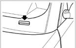
The pairs formed in the boiler comes out through the hole 4 (its diameter is 6 mm). Together with the ferry, water droplets usually fly out, which prevents the operation of the steam machine. Therefore, over the outlet, you need to install a special cap-trap 5, and it is soldered to it 6 steam pipes. Then the droplets departing from the boiler will sow on the walls of the cap, and only dry steam will fall into the nozzle.
Ready boiler check for tightness. All the sealed seams are smeared with soap foam and pour the boiler through the steam pipe. In those places where soap bubbles appear, we need a re-soldering.
Sold down the legs 7 to the boiler and bend from tin burner for dry fuel.
Steam machine is ready.
We have already said that with the right handling our steam car is completely safe. However, test precautions are not superfluous. First of all, remember that the pairs formed in the boiler should constantly leave it: consult a piston to work, and then flow through the hole in the spool plate. If this does not happen, you need to immediately repay the fire, wait when the boiler will completely cool, find and eliminate the malfunction. This Safety Rule must be strictly observed. And we advise you to invite someone from the knowledgeable adults before starting the tests.
Hose Connect the steam machine with the boiler. End hose on nozzles do not fix. So that the flame burner does not spoil the hose, wrap it with foil. Fill in a steam boiler 30-40 ml of boiled water and burn the burner with two (no more) powders of dry fuel. Slowly start turning the steam machine shaft. After about 30 - 40, the water in the boiler is covert, and hot water will be dripping from the exhaust hole. Then steam will also go out of the slot of the spool.
Properly made steam machine starts working after 1-2 minutes. Make sure that the water in the boiler does not throw out, otherwise it is squeezed.
Checked in the work steam machine, set the model. It can be ready, purchased or made with your own hands from tin or polystyrene.
Figures M. Simakova
CONTENTIntroduction 3.
Chapter 1. One-piece steam turbine 5
Chapter 2. Single Cylinder Steam Machine with Far Distribution via Shaft Krivoship 23
Chapter 3. Single Cindrovnel Steam Machine with Swing Cylinder 35
Chapter 4. Calculation of the steam machine and steam boiler 50
The voluntary society of the assistance of the army, aviation and the fleet (DOSAAF) in their organizations is widely developed by marine models. Thousands of young men and girls - members of Dosaafa - with great interest build self-propelled, sailing and desktop models of ships and ships. To make models of mass, to identify the most interesting designs, the Committees of the Company annually conduct competitions, reviews, exhibitions. In order to equalize the possibilities of competing, a single all-union classification of models has been developed and approved. Most models according to classification is self-propelled, i.e., such that is equipped with various engines.
It is especially interesting to build self-propelled marine models with steam engines. Making such a model, the designer modelist not only acquires skills, but also learns the basics of technology.
Steam engines are widespread in our folk economy. They are installed on steamers, steam locomotives, steam vehicles, lead generators in power plants.
Taking up the construction of miniature steam machines, the young designer must remember that the steam engine is Russian invention. He was constructed and built in 1765 in Barnaul, in Altai, our compatriot is an outstanding inventor Ivan Ivanovich Polzunov. Many difficulties had to survive the Russian inventor in the struggle for their idea: "Easy work on us coming." Himself hovers out, he himself referred his steam car Ivan Ivanovich Polzunov, he himself had to build it. However, to launch and test your car to the inventor and not the prize. As a result of excessive and unbearable labor, the already weak health I. I. Polzunova was very clouded, and in 1766 the Great Russian inventor died. His work continued students and followers.
In 1766, the car I. I. Polzunova was put into move and worked, leading to the movement of the blower 12 of the copper smelters, several years.
Now it is even difficult to imagine many industries and transport without steam engine.
The steam machine and modeling obtained the large distribution.
Chapter 1
One-piece steam turbine turbine design
The simplest steam engine design is one-piece steam turbine.
The main elements of the installation are the steam boiler and the steam turbine (Fig. 1).
A steam boiler is a closed vessel filled with approximately two-thirds of water volume. Under the boiler is placed furnace.
The principle of installation is the following. Water in the boiler is heated by flames and is converted to steam. As a steam formation, the amount of it increases and the pressure in the boiler rises. Paper under pressure begins to enter the steam pipe and then into the turbine nozzle.
The steam turbine nozzle represents a cone with a very small inlet. Couple, falling through a small hole into a part of a nozzle having a larger diameter, expands and its pressure drops, while its speed increases. When leaving the pair nozzle almost does not have pressure, but it comes out of it at high speed.
Thus, it becomes completely clear the value of the nozzle is to convert steam pressure energy into speed energy.
When leaving the steam nozzle meets on the path of the vane of the steam turbine and, hitting the latter, rotates the steam turbine disk. For better use The energies of the emerging pair of spatula of the steam turbine are made curved.
One-piece steam turbine (Fig. 2) consists of a housing (children. No. 1.2, 13), which rotates on the shaft (children No. 7) with blasting disk (children No. 9). The axis of the steam turbine disk is connected through a downward gear
Fig. 1. Scheme of thermal installation with steam turbine
Fig. 2. One-piece steam turbine: 1 - Ring of the steam turbine housing; 2 - housing cover; 3 - leading tribe; 4 - nut; 5 - restrictive sleeve; 6 - leash gear; 7 - shaft of the disk; 8 - nozzle; 9 - vapor steam turbine; 10 - screw; 11 - bracket axis of a leashed gear; 12 - axis of the shaft of the disk; 13 - Case cover; 14 - bracket fixing the steam turbine; 15 - steam tubes; 16 - leash (children. Nos. 3, 6) with a leash of a steam turbine (Children No. 16). Such a gear transmission is necessary to reduce the number of revolutions and increase the moment on the rowing shaft. The pair enters the turbine through the nozzle (Children No. 8), reinforced in the cover of the corps (Children. No. 13), and goes through the rejected tubes (Children No. 15), fortified in the second lid of the steam turbine (Children No. 2).
Production of details
Building a steam turbine should be started with the manufacture of the most complex parts. One of these parts in our steam turbine is a disk. Therefore, let's start building from its manufacture.
The steam turbine disk (Fig. 3, Children. No. 9) make a thick brass with a thickness of 0.4 - 0 6 mm.
Making the disk is more convenient in such a sequence. First, the workpiece is placed according to the drawing, then the central hole is drilled, as well as the holes at the base of the blades and cut the disk with scissors along the contour.
Cutting the workpiece, go to the bending of the blades. For this, it is made of a steel bar with a cross section 6x15 mm and a 50x80 mm long-length special device - Puinson (Fig. 4). The disk is put on the ends of a wooden bar and, putting a punch with a spatula, hit the hammer on it. At the same time, the blade, pressing into the end of the tree, will take the form of a punch (Fig. 5). Cutting the spatula in shape, unfold them at an angle of 15 ° to the disc plane and abill.
Fig. 5. Watching the blades using Punson
Fig. 6. Turbine Case Ring
Steam turbine blades should have sharp edges and must be well polished. This significantly increases the power of the steam turbine.
Making the disk, should go to the manufacture of the case. The steam turbine case consists of three parts: two covers and rings. First, make a ring.
Ring of the steam turbine housing (Fig. No. 6, Children. No. 1) is made from a brass strip 0.4 - 0.6 mm thick, 20 mch width and 160 mm long. To do this, take the iron or wooden blank with a diameter of 50 mm and envelop the workpiece around it. The ends of the workpiece solder and cleaned with a file and a skurt.
Go up the workpiece should be smoothly and not allowing fuses.
Fig. 7. Cover case
The cover of the steam turbine housing (Fig. 7, children. No. 2) is made of 0.4 - 0.5 mm leaf brass. Initially, cut from the sheet a round billet with a diameter of 65 mm and its edges are over-fledged on the lathe. To do this insert into the cartridge turning machine A round blank (steel or brass) with a diameter of 51 - 55 mm and for a length of 10 - 15 mm is fluttered to a diameter of 50 mm (the inner diameter of the ring ring), then it is tried. To the end of the mandrel applied the blank for the cover in such a way that its edges performed the same, and press through the ring with a rotating center (Fig. 8). By pressing the workpiece, turn on the machine and drag it to a diameter of 58 - 60 mm. Then they take a steel bar with a diameter of 10 - 12 mm and poured its end so that it has a rounded shape. After that, it is clamped into the cutting machine of the machine with a reduced end to the workpiece. By smearing the round end of the rod with oil, fade it to the edge of the workpiece and, turning on the machine, bend the edges of the workpiece, moving the sharpter to the cartridge of the lathe. If, at the same time, the edges of the workpiece loosened the mandrel loosely, then the rod should be clinging more and repeat the operation first (Fig. 9).
After this operation make marking, drill holes according to the drawing and clean the cover.
The manufacture of a second cover (Fig. 10, Children No. 13) is completely similar to the first and therefore does not require a special description.
The steam turbine nozzle (Fig. 10, Children No. 8) represents a tube, one end of which a lead plug with a tapered hole is inserted.
The end of the tube from the tube side is cut at an angle of 30 °. This cut is necessary in order for the end of the nozzle to fit as close as possible to the vanes of the steam turbine.
It is convenient to make a nozzle from a brass or copper tube with a length of 40 mm and a diameter of 3 m, one end of the tube is inserted into a lead plug to a depth of 4 - 6 mm. Before inserting a plug, the inner surface of the tube to a depth of 6 - 8 mm is cleaned with a skin and lubricate with a soldering fluid. After that, you need to make a conical hole in traffic jam. Doing the hole in the nozzle is best with a special device (Fig. 11).
A steel nail with a length of 30 - 40 mm and a diameter of 2 - 2.5 mm is sharpened at an angle of 5 - 7 ° and drive it into the board. The protruding end of the nail is rubbed with graphite (you can inhibit a pencil) and wind up the riddle asbestos. From above, on its point, leaf asbestos are applied and pressed with a wooden paler so that the edge of the nail, the punctures of the leaf asbestos, performed on top of it by 0.3 - 0.5 mm.
On the speaker end of the tip put a tube with a cork so that the tip had in the center of the cork. After that, the lower end of the tube is heated with cork. When heated, the lead cork melts and the tube from easy pressing will fall down, squeezing the rope asbestos, the turning of the wire will be included in the molten lead plug.
Lowering the tube at 7 - 8 mm, it is cooled and then removed from the nail. Since the end of the tip was grated with graphite, the lead cork will be freely with a nail, and the frozen lead forms a conical hole in the form of the island.
The smallest diameter of the hole in the plug must be 0.25 - 0.3 mm; It can be measured by a calibrated wire. If the hole nozzle turned out less, then it can be expanded by putting the tube again on the edge and hitting it slightly small hammer. After that, the end of the snot from the tube side is roasted on the cone according to the drawing and cleaned. If when the opening hole, the nozzle will be clogged with sawdust, then it should be cleaned by the same nail.
After the nozzle is made, you can proceed to the manufacture of other, simpler parts of the steam turbine.
The bracket is fixed with a steam turbine (Fig. 10, Children. No. 14) and a leash (Children No. 16) make a thickness of 0.5 - 1 mch. Their manufacture does not represent complexity and clear from the drawing.
A steam turbine shaft (Fig. 10, Children No. 7) is made of brass or steel wire with a diameter of 4.5 - 5 mm and a length of 40 - 50 mm. The workpiece is inserted into the machine, they are flying, and then drilled in it with a diameter of 1.5 mm to a depth of 25 mm. Then, pushing it with the center of the backstone, is pulled up to a diameter of 4 mm for a length of 25 mm and cut off from the workpiece with a sleeve with a length of 20 mm, which is cleaned with a file and a skurt.
The axis of the steam turbine shaft shaft (Fig. 10, children. No. 12) is made of silver or piano wire with a diameter of 1.6 mm. To do this, cut a piece of wire with a length of 8 mm and cleaned its ends. After that, the workpiece is inserted into the lathe so that it performs by 5 - 6 mm, and turning on the machine, the end of the axis is filled with a small (personal non-non-velvet) file until the axis is tightly entering the wind turbine shaft hole .
The restrictive sleeve (Fig. 10, Children. No. 5) is made from brass or divecular steel. Making it is easy and understandable from the drawing.
Screw with a nut (Fig. 10, Children. No. 10) Pick ready-made from the "Designer". If the screw is not suitable in length, then it can be cut off with a hack or wrinkle with a file.
The bracket of the axis of the leash gear (Fig. 12, children. No. 11) is made of a sheet brass with a thickness of 1 mm. From a brass leaf, a strip of 40 mm long and 10mm wide, bend it according to the drawing, drill holes, wash the file with the file and cleaned with a skin.
Fig. 12. Bracket axis axis of a leashed gear
The leading tribe (Fig. 2, Children No. 3) is selected ready from the watch mechanism or the clock mechanism of the "Designer". The tribe axis on one side is biled up to a length of 1 - 1.5 mm, and on the other to 7 - 8 mm.
In our steam turbine, a tribe with six studs from the designer mechanism is taken, but you can use a tribe and with eight studs.
Leopal gear wheel (Fig. 2, Children. No. 6) is selected prepared from the clock mechanism of the "designer" or the mechanism of the old alarm clock.
In our sample, a gear wheel was installed with forty teeth taken from the clock mechanism of the Designer. However, you can apply a toothed wheel and with another number of teeth, but it should be borne in mind that the location of the holes on the housing cover (Fig. 2, Details No. 2) Yves the axis of the axis of the leash must correspond to the distance of the tribe axes from the shaft of the disk and the gear .
In our design, the holes in the covers and in the bracket are drilled with the calculation of the gear wheel with a forty teeth and tribes with six pins.
Assembling turbine
Having made all the parts of the steam turbine, you can proceed to its assembly.
The turbine assembly should be started with the shaft supply (children No. 7) into the steam turbine disk (Children No. 9). It is most convenient to produce a shaft in the lathe centers. To do this, inserting the shaft into the disk, clamp it in the lathe centers with such a calculation so that it can be easily turned. Then "By installing the steam turbine disk at an equal distance from the ends of the shaft, the disk beat is eliminated, rotating it in the centers, and then solder the drive to the steam turbine shaft. Well reading the place of connection of the shaft with a disk, the disc is checked again by rotating it in the centers. If at the same time there is at least a slight beating, it should be fixed, flexing the disk, tapping on it with a wooden hammer. By removing the beat, the drive with the shaft is removed from the centers, the spike place is cleaned with a skin and washed with kerosene.
At the end of the shaft from the side of the nozzle (Fig. 2), the axis is pressed (children No. 12). At the other end, the shaft is inserted by the axis of the leading tribes (children No. 3). If the latter is not included, it should be chopped with a small file. The axis of the leading tribes must enter the hole of the shaft from the light blows of the hammer (dense landing). In the case when the tribe axis enters the shaft hole too easy, it should be slightly split. When opened, you need to ensure that the axis of the tribe is not brought out. A more dense landing of the axis in the hole of the shaft can be achieved, also putting several cores on the surface of the tribe axis.
Sending the axis of the tribe to the shaft hole, proceed to strengthen the nozzle in the cover lid.
When installing, it is necessary to strive to ensure that the end of the nozzle approached as close as possible to the vanes of the steam turbine disk. To find the correct position of the nozzle, you need to assemble the case. To do this, taking the housing cover and inserting the axis of the leading tribe (children. No. 3) into the central hole (Children. No. 3) to the central hole (Children. No. 12) on it, after which both covers of the hull (children No. 2 and children are put on . № 13) on the corps ring (children No. 1).
When assembling the steam turbine housing, follow the shaft axis (children No. 12) in the cover of the lid (children No. 13).
Having collected the case with the disk, in the cover (det. No. 13) is inserted nozzle at an angle of 20 ° until it stops in the spatula. In this case, the steam turbine disk is rotated for the leading tribe. If the blade of the disk is tight for the end of the nozzle, the nozzle is made by 0.3 - 0.5 mm and solder. Solding nozzle, check again, does the end of the nozzle behind the blade of the disc. If the nozzle hits the spatula, then it should be disappeared, to move a little, and then fade again.
The following are steaming tubes (children No. 15) and bracket for fastening (children No. 14) steam turbine on the model.
After the parts are soldered on the turbine housing, install a stamp gear (children No. 6).
To install the gear wheel, the lid (det. No. 2) should be removed from the housing and from the inside against the hole for the screw solder. After that, the cover is worn back to the body and, inserting the axis of the leash wheel in the cover of the cover, screw the bracket (Details No. 11). When screwing down the bracket, you should ensure that the axis of the leash wheel stood correctly and the engagement of the tribes and wheels were normal. The end of the axis of the driving wheel protruding over the bracket is soldered leash (children No. 16), after which the turbine is finally cleaned with a skin, washed in kerosene, dried and lubricated with oil.
Trying the operation of the turbine, blowing the air into the nozzle in the nozzle, is not recommended, since it will not work from this correctly the manufactured turbine.
Building a steam boiler for turbine
The simplest cylindrical boiler for one-piece steam turbine consists of the following main elements: a cylinder closed on both sides with covers, on the upper part of which the safety valve and steam pipe are strengthened; Fires and alcohols (Fig. 13). A steam boiler made of white tin or brass with a thickness of 0.25 - 0.3 mm. First, the covers of the cylinder are made (Fig. 14, children. №№6.7). They should be made in the same way as we have manufactured the covers of the steam turbine.
Then make a cylinder from the tin (Fig. 14, Children. No. 8). To do this, cut out the workpiece, then placed and cut holes for steam pipes, safety valve and chimney. After that, we enhance the workpiece on a round blank, make seams, put on the lids and peck them. When peashing, it should be especially necessary to ensure that the spike places are well warmed and tinly crushed into the joints of the joints. Then the smoke pipe is dripped into the boiler; Its edge should not appear behind the lower wall of the cylinder by more than 2 mm.
After the boiler is ready, check it on tightness. This is done like this: poured water into the boiler and, by holding a hole for steaming, into a hole for the safety valve blowing the air; If it turns out that the boiler passes water, the locations of the leaks should be well sued again.
Making sure that the boiler does not have leaks, go to the manufacture of the furnace (Fig. 14, children. Nos. 9, 10). Having made a firebox in it
Paste the boiler, dropping it into the furnace to 5 - 10 mm below the diameter. After the boiler and the firebox will be soldered, installed and solder steam pipes (children No. 1), having previously passing it through the walls of the furnace, as shown in Fig. 13. At the end of the steam pipeline, a rubber stopper with a hole is put on (Children No. 4). The manufacture of alcohol does not represent complexity and is understandable from the drawing (Fig. 15).
The most responsible steam boiler node is a safety valve (Fig. 16), which is arranged as follows. In the sleeve (det. No. 2) is inserted screw (det. No. 1). At his end, the nut (Children No. 7) was screwed, tightening through the washer (Children. No. 6) Spring (Children No. 5). Thus, the screw head presses to the plane of the spring pressure of the spring.
The sleeve is screwed into the nut (children. No. 4), which is soldered to the upper wall of the boiler on the hardening valve. Between the sleeve and the nut, the lead washer is laid (Children No. 3) for sealing.
Fig. 14. Drawings of the parts of the steam boiler: Detail M 1 - steam pipe; Detail M 4 is a rubber plug for connecting steam pipes with a turbine nozzle; Detail M 5 - chimney; parts mm 6 and 7 - cylinder lids; Detail M 8 - Cylinder Boiler; Detail M 9 - furnace; Detail N ° 10 - bottom of the furnace
The safety valve is used to prevent the break of the steam boiler from the pair pressure. With increasing pressure of steam in the boiler to critical (pressure, with an increase in which the boiler can break) the safety valve opens, part of the steam from the boiler comes out and the pressure drops. If the valve is made incorrectly, it may not be opened at critical pressure and the boiler will break. Therefore, it is very important to especially carefully consider the manufacture of safety valve details, withstanding exactly the dimensions specified in the drawings.
Valve screw (Children No. 1) and sleeve (Children No. 2) To avoid rusting and damage valve made from brass.
Details No. 4, 6, 7 can be made from both brass and steel. Washer (Children. No. 3) is made from lead. Spring valve (Children. No. 5) is wound from piano wire with a diameter of 0.5 mm. When squeezing the springs of the springs to contact with each other, the spring should be resistant to 0.6 kg. If the spring is weak, then it needs to be stretched or made new. It should be noted that the spring of the larger diameter is weaker than the spring of a smaller diameter made from the same wire.
Having made all the parts of the valve, the co-sleeve screw is torn off. The feeding of the screw to the sleeve is made as follows: the screw insert into the sleeve is inserted, having preheated the screw head with a mixture of oil with a sandpaper, and inserting a screwdriver into the screw slot, rotate it, pressing the sleeve. It is necessary to pull the screw to the sleeve until there is a solid confidence that steam at the point of contacting the screw head with a sleeve when closing the valve will not pass.
Having finished grappling, the valve is collected and regulated. The valve adjustment is in the navigation of the nut (children No. 7). When screwing the nut, the power of the spring increases, when unscrewing - decreases.
When adjusting the valve, the nut (det. No. 7) should be installed in this position so that the screw head presses to the sleeve with a power of 0.5 kg.
The screw strength of the screw head on the sleeve is very easy to determine, using ordinary weights. At the same time they do this: they take the assembled valve for the sleeve (children No. 2) and put on the weight of the scales in such a way that when lifting a cup of the valve spring, the screw head was squeezed out of the sleeve. Then, holding the valve for the sleeve strictly in a vertical position, the other cup of scales is immersed until the valve spring starts to shrink and the valve will not appear. Weight weight and determine the power of the spring pressure.
Adjusting the valve, solder the valve nut (Children No. 4) and again check the boiler for tightness. Filling the boiler with water through the valve holes, screw the valve and, turning the boiler in different directions, blur in the air pipeline of the air. Making sure that the boiler does not give leaks, you can proceed to the test of the boiler.
Testing steam boiler
A particularly important and responsible moment in modeling steam installations is the test of the steam boiler.
The test must be carried out extremely carefully that the boiler breaks could not cause an accident. On the test must be attended by the head of the mug or physics teacher.
Proceed in the following order. Filling the boiler for 2/3 volume with water, seal the outlet opening of the steam line and adjust the safety valve, navigating the nut so that the pressure of the valve head on the sleeve was three times more than with the valve operating position. If the valve spring is not able to provide such pressure, then it follows the test time to replace stronger. Then, by screwing the valve, the steam boiler is installed in the test site (in a separate room or in an open space, but with such a calculation, so that it can be moved to 15 to 20 m) and, by filling out the alcohol with technical or denatured alcohol, pre-inserting into the tube The burners of the alcohol slices are pods, put it in the firebox of the steam boiler. After making sure that the burner flame was not extinguished, from the site of the test departed by 15-20 m and leads observation. After 10 - 15 minutes, water in the boiler boils and the pair pressure will rise.
If the boiler is performed correctly, then it will withstand the steam pressure three times the worker. With a steam pressure in the boiler, three times more worker (9 atm) safety valve will open and the pressure in the boiler will continue to rise.
However, approach the tested boiler earlier than the valve closes and the alcohol will go out, should not.
After testing the boiler during three-time overload, the valve is touched and adjust again to the working position, i.e., on this position in which the valve will open from the pressure of steam in the boiler, three times the smaller pressure of steam in the boiler during the test. Adjusting the valve, the nut (children. No. 7) is soldered, after which the boiler can be installed for exploitation to the model.
Steam plant exploitation
Installing a steam boiler is better completely free, without strengthening it on the model, as it will greatly simplify the exploitation and will allow you to fill the boiler with water outside the model.
Connect steam hardware steam hardware with a steam turbine nozzle is very conveniently rubber plug, in which the hole is pre-drilled in 2.5 - 3 mm.
Fill the boiler with water follows each launch model. In no case should the model should be launched if the boiler is filled with water less than half.
The launch of the model with a small amount of water in the boiler can lead to the cutting of the boiler.
At the end of the launch of the model, the water from the boiler must be pulled out.
The axis of the turbine after launch should be lubricated machine oil - This will significantly increase the service life of the turbine. When working at full capacity, the steam turbine shaft should rotate at a speed of 7000 - 10,000 rpm.
The steam turbine, built according to our drawings, can be recommended for installation on a model of up to 1 m and displacement up to 1 kg.
Chapter 2.
Single Cylinder Steam Machine with Far Distribution through Shaft Krivoship
Device and principle of operation
In fig. 17 and 18 provides a general view of a single-cylinder steam machine with steam distribution through the shaft of the crank. It consists of the following main parts: beds, cylinder with piston, flywheel and bearing, in which the shaft rotates.
Steam machine has the following construction. On the face of children. No. 15), in its middle part, the bearing is strengthened (children No. 3), in which there are three holes: one top and two on the sides - one against the other. The top hole in the bearing is connected by steam hardware (children No. 2) with a steam machine cylinder (Children No. 12), which is reinforced at the top of the bed with two screws (children No. 1). Two tubes (children No. 4) are soldered to the side holes: one connects to the boiler, the other is an atmosphere.
The bearing rotates the crank shaft (Children No. 9), at one end of which the flywheel was naked (Children No. 7), and a coupling was strengthened on another (Children No. 5). On the shaft of the crank, against the upper hole in the bearing, there is a ring flow, from which there is a small slice to the side holes. On the opposite side of the crank shaft in the flywheel, the finger pressed (Children No. 8), shifted relative to the crank shaft and forming crank with the flywheel.
In the steam engine cylinder, the piston moves (children No. 13), moving connected by connecting rod (children No. 10) with a finger.
Works single-cylinder steam machine as follows. Through the intake nozzle connected to the boiler, steam enters the bearing. Finding on the shaft of a crank, steam on a slice enters the cylinder. In the cylinder, steam presses on the piston, moving it. Piston, moving in the cylinder, turns the flywheel of the steam machine through the rod.
When the flywheel is rotated, the slice located on the axis of the crank, moves, and at the moment when the piston is approaching the lower dead point (extreme lower position of the piston), the shaft body closes the hole, the boiler automatically turns off from the machine and steam into the bearing does not arrive.
Due to the fact that the piston told the flywheel inertia, the crank continues to rotate, moving the piston to the upper dead point (the extreme top of the flywheel).
At the moment when the piston is at the bottom of the dead point or begins to move away from it, the slice on the axis of the crank is beginning to overlap the second side opening in the bearing of the crank shaft.
When the piston moves to the upper dead point, the spent pair is pushed out of the cylinder, passes through the steam line, it falls into the groove on the shaft of the crank and, passing through the cut, is thrown out through the second side opening in the bearing of the crank shaft.
At the moment when the piston is in the upper dead point, the crank shaft is on the shaft begins to combine with a graduation side opening in the bearing of a crank shaft, a fresh working pair from the boiler enters the cylinder again, pushes the piston to the bottom dead point, and the process is repeated first.
Fig. 18. Drawing of a single-cylinder steam machine in three projections: 1 - cylinder mounting screws; 2 - steam pipe; 3 - Bearing; 4 - intake and exhaust pipe; 5 - coupling; 6 - stopper; 7 - flywheel; 8 - a finger of crank; 9 - shaft of crank; 10 - rod; 11 - finger; 12 - cylinder; 13 - piston; 14 - Ring; 15 - Stanina
Couples from the boiler can be supplied to any of the side holes in the bearing of the crank shaft, but this will depend on the direction of rotation of the steam machine shaft.
Model single-cylinder steam machine can only be built in the presence of a lathe. For convenience, a description of the manufacture of parts of the steam machine is given in the order of their numbering on the drawing of the overall view of the steam machine (Fig. 17).
Screws for fastening the cylinder (Fig. 19, Children. No. 1) are made of divecular steel. For this sang you can use the material of old screws. It is not recommended to do the screws from rivets, since this metal is very viscous and thread on the screws made of rivets are quickly triggered.
Best screws pick up ready, and if they are not suitable in length, they should be cut off.
Steam pipeline (Fig. 19, Children. No. 2) It is convenient to manufacture from brass or copper tube with a diameter of 4 mm. The cut of a tube with a length of 100 - 150 CM is bended according to the drawing, then cut the ends and cleaned. If there is no finished tube suitable sizes, It can be soldered out of tin or fine brass.
Bearing (Children No. 3) is made from a bronze rod with a diameter of 17 mm and a length of 50 - 70 mm. The workpiece is clamped into the cartridge of the lathe, leaving the end of 40 - 45 mm, and the hole is drilled with a diameter of 6.8 mm. The drilled hole is deployed to a diameter of 7 mm. Then the workpiece is treated according to the outer diameter, after which the bearing is cut off, they are traced, the side openings for the passage of steam are marked and drilled.
Inlet and outlet nozzles (children No. 4) It is better to make a 4 mm diameter from the finished tube. If there is no finished tube, you can add it on the lathe or solder out of the tin.
Coupling (Children No. 5) is pulled out of the aircraft steel or brass with a diameter of 25 mm. The workpiece is clamped into the cartridge, leaving the end 15 - 25 mm, is trimmed and drilled with a diameter of 5 mm, after which the washer is treated according to the outer contour, cut off, the hole is drilled, the thread is cut 2,6 x 0.3 and the grooves width 3 mm are cutting .
The locking screw (children No. 6) is selected ready or manufactured from steel wire with a diameter of 2.6 mm. A piece of wire clamp into vice and cut the threads 2.6 x 0.3 at a distance of 8 - 10 mm, then the sliced \u200b\u200bpart is cut off, the ends are drowned and the slot is cut down.
Flywheel (Children. No. 7) is made from any orcane steel with a diameter of 75 mm. Make a flywheel better in such a sequence. Press the workpiece into the cartridge of the lathe, is pulled up to a diameter of 70 mm, then they are trimmed, the hole is drilled with a diameter of 4.9 mm and they are deployed by a diameter with a diameter of 5 mm. Running the hole, pull the inner cavity of the flywheel and cut off. After that, by holding the flywheel again into the lathe cartridge, handle his second side. Having completed the handwheel processing on the lathe, drill a hole for a finger with a diameter of 2.5 mm.
Finger (Fig. 20, Children No. 8) is pulled out of steel wire with a diameter of 3.5 mm.
In the manufacture of a finger, special attention should be paid to the end of the finger with a diameter of 2.5 mm entered tightly into the flywheel hole.
The shaft of the crank (children No. 9) is made of a steel bar with a diameter of 7.5 - 8 mm. Treatment of a crank shaft should be performed in such a sequence. First, the workpiece is fluttered along the outer diameter of 7 mm with such a calculation so that the crank shaft is entered tightly into the bearing (Children No. 3), then the end at a distance of 7 mm to a diameter of 5.1 mm and is filled with a small file, causing to a hole with a diameter of 5 Mm in flywheel. This end must be included with the pressing of the flywheel.
Having finished the end of the shaft, make a groove of 3 μm width at a distance of 23.5 mm from the end of the shaft, after which the shaft of the crank to the bearing is torn.
The tumble of the crank shaft is made by a special ditch. It is two brass plates, the ends of which are connected by a ring (Fig. 21) with such a calculation that the plates can compress and squeeze. From the inner side on the plates there are two radial grooves, one against the other, the depth of which should be 1 - 2 mm less than the radius of the shaft of the shaft.
Treatment is processed as follows. The tritis, the grooves of which are pre-lubricated by eating with oil to the grilled surface of the shaft. Then, turning on the machine, the tread is etched on the surface being processed, compressing the plates. As you trim, you should add emery with oil.
The shaft is processed in this way until its surface becomes smooth and it will not be easy to enter the bearing. After tipping the shaft is cut off and, closing again into the cartridge of the lathe, processes the second end to a diameter of 5 mm. Then the shaft is clamped into vice and cut the cut according to the drawing.
When charging the shaft in the vice under the sponges of the vice, lead or aluminum plates should be plated.
Fig. 21. Prit
The rod (Fig. 20, children. No. 10) is pulled out of the rod steel with a diameter of 6.5 - 7 mm. First, the workpiece on the turning machine on top and drill the central hole with a diameter of 2.5 mm, then the workpiece is cut off, placed and drilled the holes for the fingers. When drilling the latter, it is especially necessary to ensure that their axes are parallel.
Piston finger (children №11) is made from piano wire with a diameter of 2 mm. The rod of piano wire is well straightened with a wooden hammer, from a well-straightened area cut off a piece of 12 mm long and the ends are well cleaned with a small file and a skin.
Cylinder (Children No. 12) is made of steel bar with a diameter of 15 mm and a length of 50 - 60 mm. The workpiece is clamped into the cartridge of the lathe so that its end of length 40 - 45 mm remains free, and the hole is drilled with a diameter of 11.8 mm to a depth of 31 mm. The donyshko holes are annked with a flat zenker and deploy a cylindrical scan with a diameter of 12 mm. If not under the hands of the zenker, you can use the same drill that drilled the cylinder opening, causing it at right angles. After processing the opening of the cylinder, the cylinder is calculated from above to a diameter of 14 mm and the workpiece is cut.
The cylinder end is wedged with a file, placed, drill holes and cut the thread 0.3x2.6.
Piston (Children No. 13) is made from bronze with a diameter of at least 13 mch and 30 mm long. Having covered the workpiece into the lathe cartridge, the holes are drilled with a diameter of 11 mm to a depth of 10 mm and the dyshko is annoying with a flat zenker. Then the piston on the outer diameter is up to 12.1 mm and processed its surface with a small (velvety) file and sandpaper. The paper should be applied to the stubble plane and then led along the treated surface, slightly pressing the file.
It is necessary to process the piston with a piston and the skin until it is free to enter the cylinder.
The piston should move freely in the cylinder, as they say, fall from its own weight, but at the same time do not pass air (if you hp the hole in the cylinder head, then the piston should stop).
It is not recommended to carry the piston to the cylinder, since when tickling, small particles eats into bronze and remain in it, developing a cylinder.
Piston liner (ring) (Children No. 14) is made of bronze or divecular steel. On the turning machine, the workpiece with a diameter and mm and a thickness of 4 mm, then the ends are placed and the two holes are drilled with a diameter of 4 mm. The metal between the holes is cut off with a round nadfyl according to the drawing. Drill a hole in the liner under a piston finger with a diameter of 2 mm follows with the piston.
The bed (Fig. 22, children. No. 15) is made of 4 mm thick sheets. First, the blank is cut along the contour of the bed, then bend according to the drawing, after which the holes are placed, they are drilled, they are lying on the file and grind the skin.
Assembling steam machine
The assembly of the steam machine should be started with strengthening the bearing of the crank shaft (children. No. 3) on the bed (Children No. 15).
The bearing of the crank shaft is soldered towards the tin soldier. To do this, place on the bearing, which is included in the hole on the bed, is listened. Then lubricate it with airy acid, after which the bearing is inserted into the hole and the place of the spike is warmed until the tin is melted and the place of the bearing connection will not fill. Having strengthened the bearing, the steam pipe and inlet and exhaust pipe are soldered.
Washing steam lines should also be soldered as the bearing, i.e., first to fill the ends of the tubes, lubricate them with etched acid and then, sticking to the place of the spike, warm it.
Warning the steam pipelines is more convenient than February, as it gives a thin flame tongue and heats only the place of the spike.
Putting the bearing and steam pipelines, the bed is cleaned with a skin and lubricate with oil. It is necessary to lubricate the oil with an oil in order to avoid its rusting from the action of injury acid.
Then go to the assembly of the crank. The crank shaft is pressed into the central hole in the flywheel so that the cut on the shaft is facing the opposite side from the hole for the finger of the crank on the flywheel. On the opposite side of the shaft into the hole on the flywheel, the finger of the crank (children No. 8) is pressed, after which the shaft of the crank in the bearing is inserted.
On the other end, the shaft is put on a leash washer and strengthen it with a locking screw. The crank with a molded leash washer should be freely and without jams to rotate in the bearing. If the crank is too tight, then it is necessary, weakening the locking screw of the leash washer, to push it away from the bearing and again secure the locking screw.
By inserting the crank and strengthening the leash washer, go to the assembly of a piston group with a cylinder. In the piston, piston liner and drill a finger hole. Then the piston finger connects the piston with the connecting rod and insert it into the cylinder. After that, the lower head of the connecting rod is put on the finger of the crank and strengthen the cylinder with screws on the top of the bed.
Strengthening the cylinder, check the quality of the steam machine assembly, rotating the shaft of the crank behind the leash washer. The crank shaft of the collected steam machine should rotate easily and without jamming. Singles can be from improving the cylinder or bearing. If when checking it turned out that there are skews, they need to be eliminated. Then check the machine in operation, for this it is attached to the steam boiler and, tugging the flywheel, start the car.
When testing the steam machine, steam may turn out that steam leaves somewhere in the spike places of the steam pipeline or runs between the bed and the cylinder head. If the couple passes through the spike places, then the seams need to succumb. In the event of a pair leakage at the scene of the cylinder head, it is recommended to pave a gasket from well-wash paper. The gasket is cut into the size of the plane of the cylinder head and do the holes for the passage of steam and screws.
After eliminating defects, the machine is attached to the motor or machine and rolled over two or three hours. Then they disassemble it, washed well kerosene, they are collected again, lubricated with oil and installed on the model.
For a single-cylinder steam machine, a steam boiler described in the first chapter of our brochure can be applied.
By installing the steam machine on the model, it must be separated from the steam boiler by partition. This is necessary so that the spent steam coming out of the steam machine can not penetrate the furnace.
After each start, the steam machine should be lubricated with machine oil. With long-term storage, the lubricant is used with thick oil (autol, solidol, etc.), and the car is recommended to clean in the washesized paper.
The test model of this steam machine showed that it can develop up to 800 rpm.
The steaming machine, built according to our drawings, can be recommended for installation on models up to 1 m long and water-displacement to 2.5 kg.
Chapter 3.
Single Cindrovar Steam Machine with Swing Cylinder
Device and principle of operation
A steaming machine with a swing cylinder (Fig. 23) has the following main parts: a bed, swinging cylinder, flywheel, crank.
This machine presents the next design. The bearing of the axis of the crank axis (children No. 19) and the bearing of the axis axis of the cylinder (Children No. 14) are strengthened on the bed (Children. No. 16). In the cylinder axis bearing head, there are six holes, two of which are on the sides of the central bearing opening and ends, without passing through 1 - 1.5 mm. The remaining holes are drilled from the end of the bearing head pairly against the vertical holes in the bearing head.
The axis of the cylinder swing rotates in the bearing (Children. No. 12). At one end of the axis there is a fungus with a cut for a cylinder and with two holes; At the other end, the restrictive sleeve is hoping (children No. 15), which holds the axis of swing cylinder from axial movement. To the excavation of the fungus of the axis of the swing cylinder of the cylinder of the cylinder (children No. 8). The holes in the cylinder are connected to the holes in the fungus of the cylinder pump axis, with the bottom hole in the cylinder connects with the holes in the fungus by simply alignment when paving the cylinder to the fungus, and the upper hole in the cylinder is connected by the hole in the fusion axis fungus of the cylinder axis with bypass channel (children. No. eleven). which solder to the cylinder and the fungus of the axis of the cylinder swing.
The cylinder is closed with covers (children. No. 5 and 9), which are tightened with each other with two screws (children No. 1).
In the bottom cover of the cylinder, in the center, there are holes for the rod passage. The steam car cylinder walks the piston (Children No. 6), motionlessly connected to the rod (Children No. 4).
Fig. 23. Drawing of the single-cylinder steam machine with a swing cylinder: 1 - screw fastening of the cylinder covers; 2 - flywheel; 3 - Finger Krivoshapa; 4 - rod; 5 - lower cylinder cover; 6 - piston; 7 - Stem cork; 8 - cylinder; 9 - the top cover of the cylinder; 10 - Couple inlet and release tubes; 11 - bypass channel; 12 - axis swing cylinder; 13 - locking screw; 14 - Bearing axis of the cylinder swing; 15 - restrictive shutting axis of the cylinder swing axis; 16 - Stanina; 17 - restrictive sleeve axis crank; 18 - crank axis; 19 - crank axis bearing
The rod of steam machine inside is facilitated and closed with a plug (children No. 7). In the lower end of the stock, a hole was drilled in which a finger (children No. 3) is inserted. Finger crank pressed into the flywheel (Children No. 2), which at the same time is a cheek crank. In the flywheel pressed the axis (children.
No. 18), rotating in the bearing (children No. 19). The free end of the axis is strengthened by a restrictive sleeve (children No. 17) with a slot for a combination with a rowing shaft.
In this design of the steam machine, when the crank shaft rotates, the cylinder is due to a fixed piston connection with a rod (connecting rod) of the steam machine will swing on the axis of the cylinder. Such a steam machine is called a machiner with a swing cylinder.
Steam distribution in a steam engine with a swing cylinder is made as follows (Fig. 24): when
The work of the steam machine is a cylinder, swinging, occupies the right and left position. In the extreme positions of the hole in the fungus, the axis of the cylinder swing is combined with holes in the bearing head of the axis of the cylinder swing axis.
In one of the vertical holes in the bearing head, steam enters and enters the end holes of the bearing, from which when combining holes, the mushroom axis axis of the cylinder enters alternately in the cylinder cavity, piston piston. Moreover, at that moment, when the pair enters the upper cavity of the cylinder, the pairs are pushed out of the lower cavity and vice versa.
It should be noted that at the moment when the piston is in the upper or at the bottom of the dead point, the cylinder must be in a vertical position and holes in the fungus of the cylinder pumping axis (Children. No. 12) should not be combined with holes in the bearing head (children. No. fourteen).
For a better understanding of the distribution of steam and the operation of the steam machine with a swing cylinder, we will analyze the specific case of connecting the steam machine to the steam boiler.
Let the pair comes along the right vertical hole in the head of the axis of the cylinder shaking axis and enters the end holes in the bearing head. Imagine that the piston is in the upper dead point, and the car flywheel rotates counterclockwise, if you look at the car from the cylinder side. The finger of the crank when rotating the flywheel will move from the upper position to the lower on the left side of the circle described by the finger of the crank when the flywheel rotation. The cylinder as the finger moves the crank from the top position to the bottom will move to the rightmost position, if you look at the cylinder side. At the time when the finger of the crank will be at the touch point of a straight line, conducted to the circle described by the finger of the crank through the axis of the cylinder swing, the cylinder will be in the extreme right position.
With the further movement of the finger of the crank to the lower extreme point, the cylinder will move to its vertical position. When the cylinder moves from the vertical position to its extreme hole in the fungus, the cylinder shaking axis will be combined with holes in the bearing head. With the extreme position of the cylinder, these holes are fully monitored. The upper hole in the fungus of the axis of the cylinder swing is combined with the upper right hole in the bearing head of the cylinder swing axis; The bottom hole in the axis fungus is combined with the lower left hole in the bearing head.
But since, through the right holes in the bearing head, fresh steam from the boiler comes from the bearing, then, therefore, steam when combining holes will enter the upper cavity of the cylinder and push the piston from the top dead point to the lower dead point. A pair, which is under the piston, will be pushed through the hole in the axis fungus, combined with the hole in the bearing head, and fall into the left vertical hole in the bearing head of the cylinder pump axis and pushed out.
Combining the holes in the fungus of the cylinder pumping axis with holes in the head of the axis axis of the cylinder axis will begin at the moment when the piston goes away from the top dead point by 15 - 20 ° at the corner of the crank the corner, and stops when the piston does not reach its lower dead point on 15 - 20 ° at the corner of the rotation of the crank.
With further rotation of the flywheel, the bottom hole in the axis fungus is combined with the inlet in the bearing head, and the upper hole in the axis fungus is combined with the left outlet in the bearing head. Therefore, in that period of time when the finger of the crank will take place on the right half of the circle, fresh steam will flow into the lower cavity of the cylinder and push the piston up. From the upper cavity of the cylinder, the spent pairs will be pushed out. By the way, it should be noted that the machine shaft when the pair inlet via the right hole will rotate counterclockwise, if you look at the cylinder side. In the event of a fresh steam into the car through the left hole, the machine shaft will rotate clockwise.
Thus, it becomes quite clear that for reversing the stroke of the machine, it is enough to switch the battery inlet into the car.
Production of details
Build a steam machine with a swinging cylinder according to the drawings, which are given in the brochure, do not provide large difficulties, but for the manufacture of parts, the lathe will necessarily need a lathe.
For convenience, the design description and the manufacture of parts is given in the order of their numbering on the drawing of the overall view of the steam machine (Fig. 23). Build parts in order of their description is completely optional and even it is recommended to manufacture more time-consuming parts first, and then simpler.
Screw fastening of the cylinder caps (Fig. 25, Children. No. 1) is made of or brass. If it is difficult to make a screw with a head of a whole piece of metal, you can take a wire with a thickness of 3 mm and a length of 40 mm, cutting the thread from both ends at a distance of 5 mm from the ends and on
One of the conders to screw the nut with a diameter of 3 mm. The hairpin with the nut successfully replaces the screw with the head.
Flywheel (Children No. 2) can be made from any oriental steel. Initially, the workpiece, clinging into the cartridge of the lathe, is calculated to the diameter of the flywheel, then the end is treated according to the drawing and drill the central hole with a diameter of 5 mm, after which the flywheel is cut off, they are cut off and drilled with a finger hole with a diameter of 2.8 mm.
Finger Krivoshap (Children No. 3) is made of silver diameter 3 mm.
Skot (Children. No. 4) is made of silver or steel brand U7a-g ~ U12A. First, the workpiece is calculated to a diameter of 6 mm with a switch of 0.1 - 0.15 mm, then the hole is drilled with a diameter of 4 mm, the diameter of the B MM is flushed, they grind the skin, carved, cut off and drill a 3-mm finger hole crank.
The bottom cover of the cylinder (Fig. 26, children. No. 5) is a sleeve with a flange for fastening. The hole of the sleeve with a diameter of 6 mm on the side of the flange is drilled by 7 mm to a depth of 10 mm. This is necessary in order to prevent the rod with the piston of the steam machine during the position of the piston at the bottom of the dead point. In the flange of the bottom cover there are two holes with a cutting 3 mm.
The bottom cover of the cylinder of bronze with a diameter of 25 mm is manufactured. First, the preparation of the workpiece to the desired diameter is shoved, then fluttered from the end to a diameter of 16 mm per 1 mm. In the center of the workpiece, the hole is drilled with a diameter of 5.9 mm and deploy 6 mm. The hole with a diameter of 6 mm is drilled with a diameter of 7 mm to a depth of 10 mm.
After processing the end and the cover holes, the outer surface is treated to a diameter of 10 mm, leaving the flange of 2 mch thickness, and cut off. Then there is a flange, drill holes, cut the thread M3 x mm and processed along the contour of the flange.
Piston (Children No. 6) is made of bronze. First, the piston with the allowance on the outer diameter is 0.5 - 1 mm. Then they put it on the mandrel, they are pulled up to size, grind and squeeze.
Stem Cork (Children No. 7) is made of brass or divecular steel. Its manufacture does not represent complexity and is understandable from the drawing.
The cylinder (children No. 8) is made of steel with a diameter of 15.8 mm to a depth of 50 mm, after which it is deployed to 16 mm. Climbing the workpiece into the cartridge, the hole is drilled, then the cylinder is touched on the outer diameter and cut off. After that, there are 0.2 mm holes and drilled holes.
The top cover of the cylinder (Children No. 9) is made of bronze or orcover steel with a diameter of 31 mm. First, the workpiece is pulled up to a diameter of 30 mm and processed its end from the spherical side according to the drawing, then the cutting cutter is treated with the second side of the cover and cut it off from the workpiece. After that, there are flange, drill holes and handle the contour of the flange.
Paper inlet and release tube (children No. 10) is cut off from the finished tube of suitable sizes or solder from the sheet material.
The bypass canal (Fig. 27, Children. No. 11) make from the tube, which first bend in half and cut in the bend. From the curved end, a blank is cut off a length of 16 MMT, the bottom of which is spilled with a file to half the diameter of the tube. If there is no finished soft tube of suitable sizes, the bypass canal can be made of a white tin or brass with a thickness of 0.1 - 0.15 mm.
The axis of swing cylinder (children No. 12) is made of steel (Art. 40 - 50) with a diameter of 20 mm. First, the workpiece is pulled up to a diameter of 3.5 mm and grind, after which the part is cut off from the workpiece, is traced, placed, drill in it with a diameter of 2 mm and cut the socket along the outer diameter of the cylinder according to the drawing.
Stop screw (Children No. 13) is made from silver or diverse steel. Its production is understandable from the drawing.
Bearing axis of the cylinder swing (Children No. 14) makes from bronze with a diameter of 27 mm. First, the workpiece is pulled up to a diameter of 26 mm, then it is triggered. After that, the central hole with a diameter of 3.5 mm is drilled. Drilling the central hole and processed the end, retreating 6 mm from the end and the bearing sleeve is pulled up to a diameter of 10 mm, then cut off and milling or poured the bearing head. Then placed and drilled holes - first two vertical, then four end.
The limiting sleeve of the axis of the cylinder pumping axis (Children No. 15) is made from the aircraft 11 -mm steel.
Stanina (Fig. 28, Children. No. 16) is made from a sheet of diverse iron with a thickness of 4 mm and a size of 35x? 5 mm. First, the edge of the workpiece is bent at a right angle, according to the drawing, the contour is placed on it and the part is cut out of it, after which they are placed and drilled holes, then the burrs are cleaned.
The restrictive sleeve of the crank axis (Fig. 27, Children. No. 17)
Made from the oscillate 11 -mm steel. First, the workpiece is pulled up to the size of the drawing, then the holes are drilled in it, in which the threads of the M SKh0\u003e 5 mm are cut and cut the groove to connect with the rowing shaft.
The crank axis (Fig. 28, Children. No. 18) is made from silver diameter of 6 mm, its manufacture does not represent complexity.
The bearing axis of the crank (children No. 19) is made from bronze.
Assembly and adjustment of the steam machine with a swing cylinder
When all parts of the steam truck are ready, proceed to the assembly of the steam machine. The assembly is more convenient to start with strengthening the bearing axis axis of the cylinder and the machine shaft bearing. The cylinder swing axis bearing is made up by vertical holes up.
Bearings are strengthened in the bed on the tin solder. When installing bearing, you should ensure that their axes are strictly parallel between themselves and perpendicular to the bed. After strengthening bearings, top steamings solder. They should be soldered by the same method that we understood when assembling the single-cylinder steam machine.
Collecting the bed, go to the assembly of the cylinder and the piston group. First, the cylinder is soldered to the excavation of the rush axis of the cylinder. The place of the cylinder, which it is attached to the excavation, is lying, then, lubricating the injury acid, pressed the cylinder to the excavation of the fungus so that the hole in the cylinder coincides with the hole in the fungus of the cylinder axis of the cylinder. After that, the spike place is incanded until the tin is melted. Solding the axis of swing to the cylinder, solder the bypass channel.
The rod is slightly pressed into the piston and the cap is driven into the hole. The plug (cork) should be tightly entering the rod and lay it out. The piston must be tightly naked on the rod. If the piston turns on the rod, then the stem connection with the piston from the tube should be sued. Then insert the piston into the cylinder, the lids wear and screw themselves with their screws. Cuting the cylinder lids, check the movement of the piston in the cylinder. The piston should be easily moving from the top cover to the bottom. If the piston is hired near the bottom cover of the cylinder, then a little screws that hold the covers and, moving
Guy covers, adjust the movement of the piston in the cylinder. After the position of the cylinder covers is found, in which the piston moves without jamming, screws tightening the covers.
Collect the piston group with a cylinder, go to the assembly of the main shaft (crank shaft) of the flywheel and the finger of crank. The main shaft and finger of crank must be well pressed in the flywheel.
After the main nodes are collected, go to the assembly of the steam machine and adjust.
Insert the main shaft of the machine into the bearing and put on the restrictive Willy sleeve, which is fixed with a locking screw.
Rotating the shaft for the flywheel, check the ease and smoothness of the rotation of the shaft. The flywheel should do 5 - 10 revolutions from one push with hand. Making sure that the main shaft of the machine rotates easily and without jamming, the axis of the swing of the cylinder into the bearing is inserted. By inserting the axis of swing, it is necessary to remember that at the same time you should wear the bottom head of the rod (connecting rod) on the finger of the crank. On the protruding end of the axis is fixed with a locking screw, the restrictive sleeve with such a calculation so that the axis of the swing of the cylinder does not have axial movements, but there was a lightness and smoothness of the stroke.
Collect the car, check the correctness of the assembly with the help of steam. For this, couples to one of the upper tubes and, putting a cylinder into a vertical position, look so that steam does not leave the other top tube and from the slot between the fungus of the cylinder swing axis and the head of the axis bearing axis of the cylinder. Then, putting alternately cylinder into the rightmost position and to the left, check whether pairs passes from under the top or bottom cover of the cylinder.
After checking the steam machine, it is running. After that, washed with kerosene, lubricate with oil and installed on the model.
Steam boiler for single-cylinder polar machine with swing cylinder
In fig. 29 shows a boiler for a steam machine with a swing cylinder. This steam boiler differs from the steam turbine boiler by the fact that the firebox is not fitted under the boiler, but behind it, and the hot gases wash the entire lower part of the boiler. By virtue of such a design, this boiler is called winter-tube. Its advantage is greater period of steam from the unit of heating area (the area of \u200b\u200bheating the steam boiler is its area, washed from the inside with water, and with outer hot gases).
A steam boiler made of leaf brass with a thickness of 0.5 mm.
Safety valve (Children No. 4), installed on the winter-tube steam boiler, it does not differ from the safety valve of the simplest cylindrical steam turbine boiler (see Fig. 16). Therefore, it is necessary to build it according to the drawings of the valve of the steam boiler.
The construction of the boiler should be performed in such a sequence. First, the cylinder of the steam boiler (children No. 3) is manufactured. For this, the cylinder is folded and the seams are peaked, then the covers are soldered and soldered (children No. 7), after which it is inserted and searched with a heat pipe (children No. 5). Saving a heat pipe, check the boiler for tightness. Making sure that the boiler is smeared well, steam pipes are soldered to it (Children No. 2), the smoke pipe (children No. 1), the plug (det. No. 8) and the firebox of the steam boiler (children. Hi 9).
The technology of manufacturing the boiler does not represent complexity and therefore is given above very briefly. Details of the boiler
And their dimensions are shown in Fig. 30, the parts of the furnace are shown in Fig. 31.
After finishing the construction of the boiler, it should be experienced and only after that install on the model.
When exploiting a steam machine with a swing cylinder, the rules recommended for a single-cylinder steam machine with distribution through the shaft of the crank.
Steam single-cylinder machine with a swing cylinder, built according to our drawings, develops 600 - 800 rpm at full capacity and can be recommended for installation on a model of up to 2 m.
Chapter 4.
Calculation of steam machine and steam boiler Definition of steam machine power
Often, the model consists of building a model under an existing ready-made steam machine. In this case, it faces difficulty choosing the size of the model.
The size of the model mainly depends on the design and type of steam machine, but from its power. Therefore, it is very important to be able to determine the capacity of an already available steam machine, without resorting to some experiments and guessings, but to find it by the formula, substituting the known values.
It should also be noted that the ability to determine the power of an existing steam machine will help the young constructor to find and the main dimensions of the steam machine when designing the car at a given power.
To determine the power of the steam machine, you need to know the following values:
1) I - the number of cylinders.
2) T - type of machine - simple or dual action.
Under the machine simple action implies the car in which the pair presses only on the one hand to the piston. A double-acting machine is called a car in which pairs pressed alternately on both sides to the piston.
3) S is the piston stroke, i.e., the path of movement of the piston from the top dead point to the bottom, expressed in meters.
4) D - the inner diameter of the cylinder, expressed in centimeters.
5) P is the pressure of steam in the boiler when the steam machine is running.
6) GG - the number of revolutions developed by the steam vehicle per minute.
Having the above values, it is not difficult to calculate the power of the steam machine.
Recall that power is work per unit time (second). Thus, the determination of the power of the steam machine is reduced to the definition of work that it can produce in one second. But in turn, the car is working because steam comes into it, and therefore the work that the machine performs, produces steam, but in a larger volume than the machine, since the work of the steam is in the straight line movement of the machine's piston. The operation of the steam machine is made due to the transformation of the straight line of the piston in the rotational movement of the shaft.
The transformation of the straightforward movement of the piston in the rotational movement of the shaft is associated with large losses in the process of mechanical transformation. As a result, the work produced by the ferry in the cylinder is much larger than the work that the steam machine can produce.
Distinguish the power of the steam machine: indicator and efficient.
Indicator power is determined by the operation of steam in the cylinder. Effective power is power on the steam machine shaft.
The indicator power of the steam machine is greater efficient. In the steam machines of the model type, the indicator power with an effective is bound by such an equation:
To determine the power of the steam machine, it is necessary to determine the work produced by the ferry per second, and then, using equation (1), determine the power on the steam machine shaft.
Model type machines are usually built with a full pair filling. This means that the steam begins to enter the cylinder at the moment when the piston is in the upper dead point or near it, and arrives until the piston reaches the bottom of the dead point or at least will be near it.
Thus, the pressure of steam in the cylinder during the movement of the piston from the top dead point to the lower remains constant and almost equal pressure in the boiler.
Indicator power is determined by the formula:
To determine the effective power of the steam machine, use equation (1).
Example. Determine the power on the shaft of the single-cylinder steam machine of a simple action, which:
Decision. At first, using equation (2), we define the indicator power of the steam machine:
Determination of the main dimensions of the steam machine at a given power
The most interesting task that you have to solve the young constructor is the design of the steam machine at a given power.
When designing, the greatest difficulty is found when choosing the main size of the steam machine cylinder, which should be selected so that the machine develops the required power.
To determine the main sizes of the cylinder of the steam machine of the specified power, it is necessary to set the pair pressure in the boiler at which the steam machine will work; The attitude of the piston's stroke to the diameter of the cylinder and the number of revolutions of the steam machine shaft.
When choosing a working pressure in the boiler, it is not recommended to make the latter to choose more than 3 atm.
The number of revolutions developed by the model type steam machine shall on average equals 500 - 1000 rpm, depending on the quality of the paper machine.
The ratio of the stroke of the piston S to the diameter of the cylinder D in the modular type machines is usually 1.5 - 2. This ratio is expressed by the formula:
By setting the pair pressure in the boiler P, the attitude of the piston running to the diameter of the cylinder to and the number of revolutions of the steam machine P and choosing the number of steam machine cylinders I and the type of action r, determine the stroke of the steam machine, using the formula:
By defining the stroke of the piston and the diameter of the cylinder, you can proceed to design the steam machine.
Calculation of the steam boiler
The main thing when calculating the steam boiler is to determine its size. The size of the steam boiler must be selected with this calculation so that it can provide the normal operation of the steam engine at full power, i.e.
Verity vapor steam boiler should be equal to the number of steam consumed steam machine. Consequently, the capacity of the boiler is directly dependent on the steam machine. But in turn, the performance of the steam boiler depends on the size of its heating area. Naturally, the larger the boiler heating area, the greater the performance of steam. The heating area of \u200b\u200bthe boiler is called its surface, washed on one side with water, and on the other - hot gases.
The productivity of industrial boilers of modern design reaches 40 - 50 kg of a pair per hour with 1 m2 of heating area. This means that a steam boiler, in which the heating area equals 1 m2, can produce 40 - 50 kg of a pair per hour.
In model-type boilers, the performance of steam with 1 m2 is significantly lower and equals an average of 5 - 10 kg of steam per hour.
The heating area of \u200b\u200bthe steam boiler for the steam machine is determined by the formula:
where 5 is the necessary heating area;
T: - the ratio of the circumference of the circumference to its diameter, equal to 3.14;
D - the diameter of the cylinder of the machine, expressed in meters; 5 - the stroke of the steam machine piston, expressed in meters; P - the number of revolutions of the steam machine per minute; i - the number of steam machine cylinders;
T - the type of steam machine (for simple action machines - 1, and for dual-action machines - 2);
Wl is a specific pair volume, i.e. volume 1 kg of steam, expressed in m3 (taken from the table, see at the end of the brochure);
W is the specific capacity of the boiler, i.e. performance with 1 m2 of heating area.
Example. Determine the size of the heating area of \u200b\u200bthe steam boiler for the machine, which has a piston stroke 5 \u003d 0.03 w, cylinder diameter 1) \u003d 0.015 g. At full capacity, the machine develops n \u003d 1000 rpm at a pressure in the p - 3 atm boiler. Machine single-cylinder and simple action.
Decision. The heating area of \u200b\u200bthe steam boiler is determined by the formula (5), but before using it, it is necessary to set the specific capacity of the pair of our boiler, that is, W, and determine, using the table, the specific volume of steam at a pressure of 3 atm boiler.
The specific productivity of our boiler will take W \u003d 10 kg of steam with 1 m2 of heating area.
Using the table, determine the specific volume of steam: WX 0.47.
Now, having all the values \u200b\u200bincluded in the right-hand formula, we find 5 - the heating area of \u200b\u200bthe boiler:
Knowing the heating area of \u200b\u200bour boiler, you can proceed to design and determine the main size of the boiler.
When designing a steam boiler, it should be remembered that its heating area is only the part of its surface, which is washed on one side with water, and on the other - hot gases.
The second and very important step of calculating the steam boiler is its calculation for strength. The calculation of the steam boiler for strength is to determine the pressure in the boiler, above which the boiler can break.
The maximum allowable pressure in the boiler is determined by the formula:
where r is the maximum allowable pressure in the boiler in the atmosphere;
N - thickness of the wall of the boiler in centimeters;
D - the diameter of the boiler in centimeters;
A - allowable voltage for the material from which the boiler is made. For iron, it is equal to 1200 kg! Cm2, and for brass - 800 kg / cm2.
Example. Determine the maximum permissible pressure in the cylindrical boiler, the diameter of which is 8 cm. Made a brass boiler with a thickness of 0.5 mm.
Decision. The maximum allowable pressure in the boiler is determined by the formula (6), it is equal:
This means that the increase in the pressure in the boiler above 10 atm can lead to the rupture of the steam boiler.
Explorate the boiler at a pressure equal to the maximum permissible pressure is strictly prohibited. Everyone
The model boiler should work with a three-time storage margin. This means that the working pressure in the boiler should be equal to! / S extremely permissible pressure.
With the increase in pressure in the boiler for 1/3, a steam boiler safety valve should be opened.
The calculation of the safety valve is the third step of calculating the steam boiler and is to determine the pressure of the valve spring. Valve spring pressure pressure is by the formula:
where F is the power of the pressure of the valve in kilograms;
1c - the ratio of the circumference of the circumference to its diameter, equal to 3.14;
D - valve diameter in centimeters;
P is the pressure in the boiler at which the valve must open.
Example. Calculate the valve spring pressure force, if it is known that the maximum pressure in the boiler should not exceed 3 atm.
Internal valve diameter D \u003d 5 mm.
Decision. Spring pressure force is determined by formula (7):
The above calculations, despite their primitiveness, will help young designers to get used to the technical analysis of their designs, to a competent assessment of machine parts, to a reasonable choice of the basic sizes of model steam installations.
|||||||||||||||||||||||||||||||||
Recognition of text books with images (OCR) - Creative Studio BC-MTGK.
Toy of our grandpa
Dilute pairs!
This will not hear such a competition today. Meanwhile, in the 20s of the 20s, many models used on ship, auto and even aircraft models of the steam engine. Steam machine with a swing cylinder was most popular. It is easy to manufacture ... However, we will provide the word Az Toro - modelist Alexander Nikolayevich Ilyina: at the request of the editorial office, he made and experienced a ship with such an engine.
Reliability and safety are the main criteria that I was guided by choosing the type of steam machine. A steam engine with a swing cylinder, as the tests have shown, with the correct, neat production of the model, withstand even twice overloads.
But no wonder I emphasized accuracy - in it the key to success. Try to accurately fulfill all our recommendations.
Now let's talk about the steam engine itself. Figures I and II show the principle of its action and device.
On the bed 11, the cylinder (parts 1, 2 and 13) with a spool plate 8 are highly strengthened. For the input and exit of steam in the cylinder and the spool plate, a hole was drilled 3. In addition, another spool plane is installed on the bed.
style 4. Two holes are drilled in it. In the process of operation of the steam engine, when the cylinder hole is aligned with the right opening of the spool plate 4, the pair enters the cylinder (see Fig. I, phase a). Expanding steam pushes the piston 13 down - to the so-called lower dead point (phase b). Thanks to the flywheel 9, the piston movement at this point will not stop dried by inertia, it rises up, pushing the spent steam. As soon as the opening of the cylinder coincides with the left hole of the plate 4, the pairs will go out into the atmosphere (phase B).
Slot plates, as you understand, should be tightly adjacent to each other, otherwise steam will penetrate the gap and the engine efficiency will noticeably decrease. Therefore, on the axis 7, the spring is installed, pressing the plate 4 to plate 8. In addition to the main function, this node also performs the role of a safety valve. When the pressure in the boiler for any reason increases, the spring will be squealing, the plates will disperse and excess the pair will come out. Therefore, the spring is tightened with nut so that the engine shaft can make several inertia revolutions. Check it out by turning it with your hand.
Couples in the car enters through
5 "Young technician" № 2
Ehre Wem Ehre Gebührt👍🏻bin Wilder Fan Aber Man Muss Zugeben Er Hat Leider Keine Chance Gehabt Glückwunsch Furnry
Schaut Euro Mal Den Boxkampf Richtig An Und AB Dieser Zeit Als Wilder Am Ohr Getroffen Wird Dreh Er Sich Bei Jedem Schlag Von Fury Weg Nicht Normal Mehr🙏
Ach Ja ..... Ali Is The Greatest
OK Er Hat Gewonnen (Durch Einen Treffer Der Wilder Das Gleichgewicht Genommen Hat, Das Kann Im Schwergewicht Immer Passieren), Nun Einmal Ehrlich, Was Für Ein Niveau IST ES Insgesamt Für Das Boxen? EBEN, ES IST Erbärmlich Im Vergleich Zu Wirkliche Guten Boxern und Boxkämpfen.
Dann Lieber Syncronschwimmer Der Männer Ansehen .... Da Ist Mehr Feuer Drin
Fury Super LEISTUNG👍 ABER ALLE DIE JETZT WILDER ABSCHREIBEN LANGSAM ??? Das War Nicht Mehr Wilder Nach Dem Treffer Am Ohr Kein Gleichgewicht Mehr Und So Kein Richtiger Stand Zu Boxen Das Ist Sehr Übel Im Kampf und Ein Grosser Nachteil.
Wilder Auf Dem Boden Zusehen Tut Weh Als Fan😥
Wilder Hat Den Kampf Verkauft So Schlecht Kann Doch Net Sein Ernst Sein !!
Ali Oder Tyson Würden Die Beiden Zerlegen
Wilder Zu Inaktiv Und Unbeweglich - Nur Auf Den Einen Schlag Warten Is Zu Wenig
Der TYP AUF DEM THRON IST KNOSSI 😂😂
Mike Tyson Hätte Sich Nie Im Leben Von So Einem Weißbrot Fertig Machen Lassen .... So Geht Das Nicht Weiter Ich Kündige Hä
Voll Komisch Alles.
Weiß Man Schon Wilder Erlitten Hat Weiß Man Schon Wilder Erlitten Hat?
Soll Das Wirklich Boxen Sein? Hat Sich Wie Die Musik Von Heute Entwickelt
BEST WRESTLING FIGHT 2020! No Boxing.
Fry Wieder Mit Diesem Spritzen Psychopath
EKELHAFTER TYP DER FURY
Der Herr SEGNE DICH DU MACHST EINEN TOLLEN JOB UNSERN JESUS \u200b\u200bZU VERKÜNDEN
Habe Dazn Gerade Gekündigt. Die Haben Alle Meine Daten, Kontonummer, Adresse, Geburtsdatum, Aber Ich Konnte Den Kampf Nicht Gucken, Weil Ich Keinen Deutschen Pass Habe! ABSOLUT PEINLICHER LADEN!
Wilder Wurde Raw Doggy Genommen
Wilder BleiBT NO1!
Beide Waren Gut Aber Fury War Diesen Kampf Einfach Besser Aber Ich Glaube Wenn Fury Ihn Nicht So am Ohr Getroffen Hätte Wäre der Kampf Anders Ausgegangen
Vallah Wilder Wild Ihn Noch Auseinander Nehmen
Ich Feiere Beide Boxer, Ich Weiß Nicht OB Ich Mich Freen Oder Ärgern Soll .. Bin Einfach Nur Froh, Dass Wir Zwei So Großartige Boxer Haben Und Sowas Überhaupt Erleben Dürfen! Respekt An Beide GG Fury
Uff Die Deutsche Profi Boxer Community Wie Lächerlich Alle Auf Einmal Voll Profis Geworden Kennen Sich Am Besten Aus. XD Na Dann Ihr Internet Rambos Boxt Mal Gegen Wilder Klappt Sicher;)
AJ VS Fury Und Ich Sage Euch Voraus: AJ GEWINNT.
Crazy, Schade Das Wilder Verloren Hat, Aber Fury Verdient Gewonnen. 🥊🥊🥊👊🏼👍🏼
trotzdem Respekt An Wilder .. Die Ersten 2 Runden Waren Relativ Ausgeglichen. Aber Nach Dem Ohr Treffer War Wilder Nicht Mehr Da Auber Konnte Trotzdem Auf Beinen Stehen. Wer Weiss Wie Lange Er Noch Ausgehalten Hätte Wenn Kein Handtuch Geflogen Wäre.
Wilder Hat So Viel Gelabert Aber Dann ReingeSchissen
Was Für Ein Scheiss Habt Ihr Denn DA ZUSAMMENGESCHNITTEN 😄😄😄😄 ???
Fury WUSSTE DASS DAS TROMMELFELL VON WILDER GERISSEN IST UND HAT DAS SELBSTVERSTÄNDLICH AUSGENUTZT, WIE ES JEDER GEMACHT Hätte. Hätte Trotzdem Gerne Gewustst Wie Der Kampf Ausgegangen Wäre, Hätte Wilder Nicht Dieses Handicap Gehabt. TROTZDEM RESPEKT AN FURY. Glanzleistung!
SELTSMSTER MENSCH AUF DIESEM PLANETEN
KirmesBoxer Genau Wie Die Klitschko's. Sollten Besser Im Zirkus Auftreten. TYSON, HOLLYFIELD, LEWIS DAS WAREN BOXER. Schade Das Der Boxsport Geschichte IST.
Dafür Bin Ich Wach Geblieben, Fury der Dreckste Boxer Aller Zeiten. Der Box AUFM HINTERKOPF / OHR WAR SCHONKOPFF / OHR WAR SCHON LINK, SELBE BEI \u200b\u200bKLITSCHKO GEMACHT MEHR ALS DRECKIG SEIN KANN DER NICHT.
Fury IST Maschine
Tschipsi-King, Soso
Alhamdulilah ☝️
Wo Sind Die Richtigen Jungs Von Damals ... Heute Nur Noch Steifes Schachspiel .....
HTML Checkt Meinen Neuen Beat
SEHR SCHADE DAS Wilder Nicht Gewonnen Hat. Leider Hat Ihn der Lucky Punch Getroffen Und Danach War Er Einfach Ko. Passiert Halt Im Schwergewicht Aber Extrem Bitter Für IHN. Vieleicht Solte Er Nun Seine Karriere Beenden. Was Soll Er Noch Groß Gewinnen Nun ?? In Kampf 3 Wird Es Bestimmt So Laufen Wie Gegen Otto Wallin. Da Muss Er Dann Gegen Die Ring Und Punkte Richter Boxen. Da Kann Er Eightlich Nur Verlieren und Joshua Wird Sich Ihm So Oder SO Nicht Stellen. Wozu Noch Unnötig Kämpfe Gegen DurchschnittsBoxer ?? (White Und CO). Außer Zum Geld Verdienen Lohnt Sich Das Für Ihn Nicht. MIT EINER NIEDERLAGE KANN MAN AUFHÖREN UND SEIN GESICHT WAREN. War Doch Eine Erfolgreiche Karriere Und 1 Kampf Kann Man Mit Pech Mal Verlieren. ER KANN STOLZ SEIN AUF DAS WAS ERREICHT HAT.
UND ER WILL EINEN JUNGEN MIKE TYSON BESIEGEN?
Tyson Fury: Sieht Aus Wie Ein Großer, Unsportlicher und Langsamer TYP - und IST DAS EXAKTE GeGenteil Davon. Stark, Ausdauernd, Schnell, Präzise.
SO SCHADE DAS SO EIN ATHLETISCHER AFROAMERIKANER DER SEHE GROß IST, MEINER MEINUNG NACH GEGEN SO EINEN FRECHN SCHWABBEL TANTE ZU VERLIEREN. SEHR SCHADE 😾
Damit Fury Überhaupt Noch Kämpfen Darf Der Scheiß Kokser
wAS IST DAT DENN FÜR NE PEINLICHE KASPER SHOW
Schnapp Im dieter Johnny? 😎
Glückwunsch an Fury, verdienter Sieg ... finde auch gut das Wilder beim Interview nicht auf das Ohr eingegangen ist sondern klar gessgt hat: "der bessere Mann hat heute gewonnen", aber Wilder hat Herz bewiesen und ne menge eingesteckt und nochmal für alle zum mitschreiben, Wilder hat ein TROMMELFELLRISS, damit ist überhaupt nicht zu spaßen und erst recht nicht im Boxen, wenn das Gleichgewicht durch so eine verletzung so beeinträchtigt wird, ich glaube wir hätten ohne die verletzung ein sehr spannenden Fight gesehen, bin gespannt auf den 3. Kampf der Beiden.
canyoMakeit.redbull.com/de-de/applications/1716 Hi Freunde, Wir Sind Team NRG Und Haben Die Redbull Challenge Can You Make IT? Mitgemacht.wir Vertreten Team Deutschlamd Sowie Rwth Aachen Uni.wir Brauchen Eure Unterstützung und Würden Uns Freenn Wenn Ihr Für Unser BewerbungsVideo Durch Den Obigen Link Voten Würdet.nrg Dankt Euro! 😍
Ich weiß nicht wirklich was ich von dem Kampf halten soll .... Viele Schläge auf den Hinterkopf und der Abbruch, es bleibt abzuwarten wie schwerwiegend die Innenohr Verletzung ist ... Sollte es keine gravierende Verletzung sein, war der Abbruch zu früh. Im Ersten Kampf Hätte der Ringrichter Auch Sofort Abbrechen Können, Als Tyson Besinnungslos da Lag + Das Blut Gelecke War Irgendwie Drüber. Weiß Auch Immer Noch Nicht Was Ich Von Tyson Halten Soll, Mann der Comebacks Und Trotzdem Ein Komischer Kautz
Die Zerstörung ..
McGregor vs Fury Has To Happen !!
Check Mal Mein Kanal AB Bitte
Hätte Echt Keiner Gedacht Das Er SO Stark Kämpft 👍🏾☝🏼
Gekaufter Kampf Wilder Boxt Viel Anders
Tyson Fury IST So Ein Echter Rocky Balboa Charackter
Pech Für Wilders, Daß Sein Trommelfell Platzte. DA KONNTE ER NUR NOCH WEGEN DEM KOMPLETT AUSGEFALLENEN GLEICHGEWICHTSSINN DURCH DEN RING TAUMELN. Ich Hatte Das Auch Schon Und ES IST DAS AUS! Schade!
Owners of the patent RU 2705704:
The invention relates to mechanical engineering, in particular to four-stroke engines of internal combustion, and can be used in the transport and stationary engine. The invention is aimed at improving the durability, reliability and efficiency of the engine by reducing its wear. This is achieved by the fact that the four-stroke internal combustion engine with a swing cylinder comprises a fixed body 1, on which the piston 4 is mounted through the crank-connecting mechanism 2, and the capability of the cylinder 12. The cylinder is made inlet 14 and the outlet 15 channels and the corresponding valves them 16 and 17, Ignition Candle Hole 19 and a snoring 22 Wheel with four teeth, in which the protrusions of the intake 27, release 28 and ignition are made. On the housing two dogs 6 and 7 of the gas distribution mechanism are installed and an inlet for combustible mixture 8 and Outlet 9 for exhaust gases. 9 yl.
The invention relates to mechanical engineering, in particular to four-stroke engines of internal combustion and can be used in a transport and stationary engine building.
Four-stroke internal combustion engine with forced purging (Patent of the Russian Federation for invention No. 2310080, publ. 10.11.2007, Bul. No. 31) containing Carter (body), cylinder with ring-shaped cavity, crankshaft with two eccentric, pistons, connecting rods, head Cylinder and gas distribution mechanism. The cylinder with an annular cavity and a petal valve in the inlet canal is installed on the crankcase. Crankshaft It is connected by the main connecting rod with the working piston, and additional connecting rods are installed on the crankshaft eccentrics associated with the ring-shaped purge piston. The inlet channel of the cylinder head is connected by means of a connecting channel with a volume formed by the ring-shaped cavity of the cylinder and the ring-shaped purge piston.
The four-stroke engine of internal combustion (Patent of the Russian Federation for the invention No. 2028471, publ. 02/09/1995), which contains a cylinder placed in it the piston associated with the crankshaft with a connecting rod, crankcase, communicated with the atmosphere with an intake channel with a locking body and bypass channel with inlet and outlet holes, located with the possibility of connecting the crankcase cavity with the combustion chamber at the position of the piston at the bottom of the dead point, and the feed valve is installed in the inlet, and the output is equipped with a locking organ made in the form of a cylindrical spool sleeve associated with Cracked shaft with ball hinge.
The disadvantage of famous engines is the high wear of the piston and the cylinder, which leads to a decrease in the durability, reliability and efficiency of their work.
The invention is aimed at hanging the durability, reliability and efficiency of the engine by reducing its wear.
This is achieved by the fact that the four-stroke internal combustion engine with a swing cylinder contains a fixed body, which is installed with a piston through a crank-connecting mechanism, and the possibility of swing a cylinder. The cylinder is performed intake and outlet channels and the valves corresponding to them, the ignition candle hole and the ratchet wheel with four teeth is installed, on which the protrusions of the intake, release and ignition are made. On the housing, two dog distribution mechanisms are installed and an inlet for a combustible mixture and an outlet for exhaust gases is made.
The essence of the proposed invention is illustrated by the drawings in FIG. 1 shows the appearance of the engine; FIG. 2 - a-A section FIG. one; FIG. 3 - top view in FIG. one; FIG. 4 - section B-B FIG. 3; FIG. 5 - section B-in FIG. 3; FIG. 6 is the top view of the cut D-D FIG. 1 on the cylinder; FIG. 7 is the bottom view of Mr. FIG. 1 on the ratchet wheel; FIG. 8 - view of the protrusion on the ratchet wheel on the side; FIG. 9 - Engine operation scheme.
The four-stroke engine of internal combustion with a swing cylinder contains a fixed body 1, on which the crank-connecting-connecting mechanism 2 is located with flywheel 3 and piston 4 with a rod 5. On the body 1, two dogs 6 and 7 of the gas distribution mechanism are installed and an inlet 8 for a combustible mixture is made. and outlet 9 for exhaust gases with two spools, respectively, 10 and 11. Cylinder 12 is mounted on the housing with the possibility of swinging on two supporting semi-axles 13. The cylinder is made in the cylinder 14 for the combustible mixture and the exhaust channel 15 for exhaust gases in which Installed inlet valve 16 for combustible mixture and exhaust valve 17 for exhaust gases. Rollers 18 are located on the rods of the valves 16 and 17, the ignition candle holes are made and the ignition contact is installed 20. The axis 21 is fixed on the cylinder, on which the distribution wheel 22 of the gas distribution mechanism is installed 23, 24, 25, 26. On the ratchet wheel are made The protrusion protrusion is 27 combustible mixture, output of 28 exhaust gases and ignition protrusion 29 for closing the ignition contact 20.
Swinging on the supporting semi-axles 13 during the engine operation, the cylinder performs an oscillatory movement - one complete oscillation for one turnover of the crank-connecting mechanism, and the ratchet wheel installed on the axis during this time takes half turn. Thus, for two turns of the engine flywheel, the ratchet wheel makes one turn, which makes it possible to install gas distribution and ignition control and ignition controls on a ratchet wheel with a four-stroke engine operation cycle.
The engine works as follows.
When the engine is running, the piston 4 performs a reciprocating movement inside the cylinder 12, and the cylinder 12 swings on the support semi-axes 13, while the ratchet wheel 22 mounted on the axis 21 in the top of the cylinder 12, with the help of dogs 6, 7 performs rotational motion around Axis 21 and protrusions 27, 28, 29 controls the intake valve 16, exhaust valve 17 and the contact of the ignition 20. Thus, the four-stroke engine operation cycle is carried out.
Right position (Fig. 2, Fig. 3).
The piston 4 is in the upper dead point, and the axis 21 of the ratchet wheel 22 is in the middle position, while the dog is tightened for the tooth 26, and the dog is 7 for the tooth 24, and the protrusion protrusion 27 and the protrusion of 28 ratchet wheels 22 are located, that they do not press on the rollers 18 inlet valve 16 and the exhaust valve 17, that is, they are closed.
Inlet tact (figure 9).
From the initial position of the flywheel 3, having a moment of inertia from the previous cycle, it turns counterclockwise from 0 ° to 90 °, while the cylinder 12 turns along with the axis 21, and the ratchet wheel 22, held by the dog 6, rotates around the tooth 26, and The dog 7 comes out of the engagement with the tooth 24, and so as long as the dog is engaged in engaging with the tooth 23, while the ratchet wheel 22 turned from 0 ° to 45 °. At the beginning of the rotation, the ratchet wheel 22 by its protrusion 27 runs on the roller 18 inlet valve 16 and opens the valve. Next continues intake tact. Flywheel 3, continuing the movement counterclockwise from 90 ° to 180 °, while the cylinder 12, together with the axis 21, turns to the left, and the ratchet wheel 22 is injected with a dog 7, turns around the tooth 23, and the dog 6 comes out of the engagement with the tooth 26, and So as long as the dog 6 does not engage with the tooth 25, while the ratchet wheel 22 turned from 45 ° to 90 °. When the roller 18 comes down from the speck of the inlet of 27 ratchet wheels 22, the intake valve 16 is closed. At this intake tact, the compression tact begins.
Compression tact (Fig. 9).
Flywheel 3 turns counterclockwise from 180 ° to 270 °, while the cylinder 12, together with the axis 21, turns left, and the ratchet wheel 22, held by the dog 7, turns around the tooth 23, and the dog 6 comes out of the engagement with the tooth 25, and so As long as the dog 6 does not engage with the tooth 24, while the ratchet wheel 22 turned from 90 ° to 135 °. Next continues compression tact. Flywheel 3, continuing the movement counterclockwise from 270 ° to 360 °, with the cylinder 12, together with the axis 21 turns to the right, and the ratchet wheel 22, held by the dog 6, turns around the tooth 24, and the dog 7 comes out of the engagement with the tooth 23, And so as long as the dog takes it to engage with the tooth 26, while the snoring wheel 22 turned from 135 ° to 180 ° and its ignition protrusion 29 closes the ignition contact 20. Begins the working stroke tact.
Tact of the working stroke (Fig. 9).
Flywheel 3 turns counterclockwise from 360 ° to 450 °, while the cylinder 12, together with the axis 21 turns to the right, and the ratchet wheel 22, held by the dog 6, turns around the tooth 24, and the dog 7 comes out of the engagement with the tooth 26, and so Until then, the dog takes it to engage with the tooth 25, while the ratchet wheel 22 turned from 180 ° to 225 °. Next continues the battery of the working stroke. Flywheel 3, continuing the movement counterclockwise from 450 ° to 540 °, while the cylinder 12, together with the axis 21 turns to the left, and the ratchet wheel 22, held by the dog 7, turns around the tooth 25, and the dog 6 comes out of the engagement with the tooth 24, And so as long as the dog 6 does not engage with the tooth 23, while the ratchet wheel 22 turned from 225 ° to 270 °. On this stroke tact, the issue tact begins.
Release tact (Fig. 9).
Flywheel 3 turns counterclockwise from 540 ° to 630 °, while the cylinder 12 along with the axis 21 turns to the left, and the ratchet wheel 22, held by the dog 7, turns around the tooth 25, and the dog 6 comes out of the engagement with the tooth 23 and the release of the release 17 ratchet wheels 22 runs on a roller 18 of the exhaust valve 28, and so until the dog is engaged in engagement with the tooth 26, while the ratchet wheel 22 turned from 270 ° to 315 °. Next continues the issue tact. Flywheel 3, continuing the movement counterclockwise from 630 ° to 720 °, while the cylinder 12 along with the axis 21 turns to the right, and the ratchet wheel 22, held by the dog 6, turns around the tooth 26, and the dog 7 comes out of the gear with the tooth 25, And so as long as the dog takes it to engage with the tooth 24, and the ledge of the release 17 of the ratchet wheel 22 will drive from the outlet 18 of the exhaust valve 28, and the valve will close, while the ratchet wheel 22 turned from 315 ° to 360 °. This is completed on this tact. The engine has come to its original position.
Thanks to the proposed technical solution, which ensures the swing of the cylinder along with the piston, the eccentricity of the crank-connecting mechanism is excluded and the friction between the cylinder and the piston decreases. This in turn increases the durability, reliability and efficiency of the engine.
The four-stroke internal combustion engine with a swing cylinder containing a fixed body, which is installed connected to the piston through a crank-connecting mechanism, and the possibility of swing a cylinder, with the intake and outskirts of the inlet channels and the corresponding valves, the ignition candle, and the installed ratchet wheel with four The teeth on which the protrusions of the intake, release and ignition are made, and two dog distribution mechanisms are installed on the housing and the inlet for combustible mixture and the outlet for exhaust gases is made.
Similar patents:
The invention relates to the engine, in particular to the creation of internal combustion engines. The engine contains a hollow rod connecting the pistons, made with a diameter equal to the piston diameter, and equipped with zigzag, symmetrical, closed grooves of the rectangular cross section on both sides of the oblong hole for the passage of the intake pipeline in its central part, with which the rollers mounted in the hubs of two Coaxial rod of the conical gear on rolling bearings, which are combined with each other of the third conical gear, transmitting torque to the power take-off shaft.