Gear shift diagram Models of gearboxes (gearboxes) installed on MAZ vehicles Gear shift diagram for MAZ 8
3.2. Gearbox and its drive. Device.


MAZ vehicles are equipped with an eight-speed dual-range YaMZ-238A gearbox with synchronizers in all gears except reverse. The gearbox consists of a main two-stage gearbox and a two-stage additional gearbox (reduction gear).
The gearbox structure is shown in Fig. 44. Installation of all gearbox parts is carried out in the housings of the main and additional gearboxes, which are interconnected and then assembled to the clutch housing; a single power unit is formed consisting of the engine, clutch and gearbox.
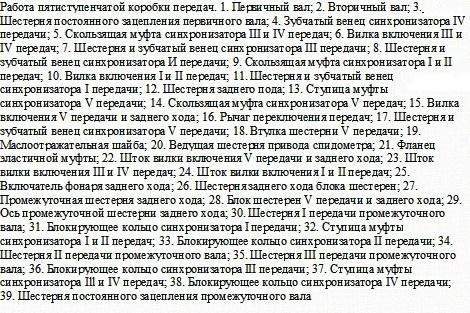
The primary shaft 1 of the main box is mounted on two ball bearings; Driven clutch discs are installed at the front splined end, and the rear end is made in the form of a ring gear of the constant mesh gear of the main gearbox.
The secondary shaft 5 of the main box is supported at the front by a cylindrical roller bearing installed in the bore of the gear ring of the drive shaft, and at the rear - on a ball bearing mounted in the front wall of the crankcase of the additional box. The rear end of the secondary shaft is made in the form of a ring gear, which is a constant meshing gear of the additional gearbox.
The gears of the second and fourth gears of the secondary shaft of the main box are mounted on sliding bearings made in the form of steel bushings with a special coating and impregnation, and the first gear and reverse gears are mounted on roller bearings.
The intermediate shaft 26 of the main box is supported at the front by a roller bearing mounted in the front wall of the main box crankcase, and at the rear - on a double-row spherical bearing placed in a cup mounted in the rear wall of the main box crankcase. An additional axle for the reverse intermediate gear is installed in the crankcase bosses of the main box. The reverse gear is engaged by moving the reverse carriage 24 forward until it is connected to the ring gear of the reverse gear 25, which is in constant engagement with the reverse intermediate gear.
The secondary shaft 15 of the additional box is supported at the front by a cylindrical roller bearing located in the bore of the gear rim of the secondary shaft of the main box, at the rear - by two bearings: a cylindrical roller bearing and a ball bearing, installed respectively in the rear wall of the crankcase of the additional box and the bearing cover of the secondary shaft.
Gear shift synchronizers are installed on the splines in the middle part of the secondary shaft of the additional box, and on the rear spline end there is a driveshaft mounting flange. On the middle cylindrical part of the shaft, gear 11 of the additional box is installed on cylindrical roller bearings.
The intermediate shaft 19 of the additional box is supported at the front by a cylindrical roller bearing installed in the front wall of the crankcase of the additional box, and at the rear - by a double-row spherical bearing located in a cup mounted in the rear wall of the crankcase of the additional box. A reduction gear 22 is installed on the front splined end of the intermediate shaft of the additional box. At the rear of the intermediate shaft there is a gear ring, mated to the reduction gear of the secondary shaft of the additional box.
To engage gears, inertial synchronizers with conical friction rings are used in the main gearbox, and with friction discs in the additional gearbox.
Gear shifting in the main box is carried out using a mechanical remote drive, and the additional gearbox is controlled using a pneumatic drive
Remote drive of the main box (Fig. 45).


Telescopic type, consists of a mechanism located directly on the gearbox 13, and a system of rods and levers connected to the 3 gear lever mounted in the cabin.
Three rods are mounted in the lugs of the top cover 1 (Fig. 46) of the main box: on the far right (along the direction of the car) there is a reverse gear fork 3, on the middle one there is a fork 4 for switching the first and second gears of the main box, and on the third there is a fork 8 shifting the third to fourth gears of the main box.
Rods 5, 20 and 21 move in the guide supports of the top cover using lever 22. There are heads (11 and 17, respectively) on the reverse rod and the shift rod for the first and second gears of the main box. The lever 22 enters directly into the head 17, and into the head 11 through the reverse shift lever 15.
To engage the third and fourth gears of the main box, the lever 22 can fit directly into the groove of the fork 8 for shifting these gears. The position of the reverse rod is fixed in the cover with the help of a fuse 16, which is included in the driver 15 under the action of a spring 12 placed in a special glass 13. Only by overcoming the force of the spring of this fuse can reverse gear be engaged. The rods are held by ball clamps when the gear is engaged and in the neutral position. To prevent the possibility of simultaneous engagement of two gears, a special ball-type lock is installed in the rods.
On the top cover of the main box there is mounted a housing 11 (see Fig. 45) of the remote control mechanism for the main box, in which there is a gear shift shaft 12 with a lever 14 fixedly fixed on it and an intermediate lever 18 connected to the longitudinal rod 7 of the remote drive.
In the housing of the remote mechanism there is a ball retainer 9 for gear selection. The longitudinal rod 7 can perform both longitudinal and angular movements. The angular movement of the rod causes axial movement of the shaft 12, which leads to the connection of the lever 14 sitting on it with a certain slider in the upper cover of the main box 13. The movement of the longitudinal rod causes the rotation of the gear shift shaft 12 and the lever 14 sitting on it. In this case, the gear shift fork rod moves together with the fork until the corresponding gear is engaged.
The additional box is controlled using a pneumatic valve by range switch 1 (see Fig. 45), located on the handle of gear shift lever 3.
Switching mechanism for the additional box (Fig. 47).


It consists of a pressure reducing valve 12, an air distributor 6, a pneumatic valve 5, an inlet valve 8, a working cylinder 1 and air ducts.
Reducing valve 3 (Fig. 48) serves to reduce the pressure of compressed air supplied from the vehicle’s pneumatic system to 4.75 kgf/cm² - the working pressure of the gearbox pneumatic system. The air distributor 23 directs compressed air from the inlet valve 17 into one or another cavity of the working cylinder 25 and bleeds air from its cavities.
Pneumatic valve 5 controls the air distributor. When the 6-range switch is lowered down, the air distributor spool is set to the position corresponding to direct transmission in the additional box. With the switch raised, move to the downshift position.
The inlet valve 17 ensures the supply of compressed air through the air distributor 23 to the working cylinder 25 only when the gear in the main box is turned off. When the gear is engaged in the main box, the valve inlet is closed by pusher 16 and air does not enter the air distributor and the working cylinder, the relief hole in the valve body is open, both cavities of the working cylinder are connected to the atmosphere.
When range switch 1 is raised (see Fig. 45), cable 6 moves spool 3 (Fig. 49) to a position in which compressed air supplied from the pressure reducing valve to channel A through the pneumatic valve channel enters channel B and then to the air distributor at engaging downshift. Channel B at this time is connected to the atmosphere through filter 8.

When the range switch is lowered, the cable moves spool 3 to a position in which compressed air through channel A enters channel B and from there to the air distributor to engage direct transmission. At this time, channel B is connected to the atmosphere through cover 5.
The gear shift mechanism of the additional box is located in the upper cover of its crankcase. Here there is a rod 13 (see Fig. 44), connected to the piston of the pneumatic cylinder 14. The direction of movement of the rod with the gear shift fork 10 of the additional box attached to it depends on the pressure supplied to the pneumatic cylinder to the left or right of the piston, which causes the inclusion of the large 20 or small 21 synchronizer, i.e., reduction or direct transmission of an additional box.
A synchronizer sensor for downshift engagement is installed on the top cover of the additional box. When the rod 13 and fork 10 of the gear shift of the additional box are moved from one position to another, a control light connected to the switch terminal 35 lights up in the driver's cabin. The light goes out as soon as the selected (direct or downshift) gear is fully engaged.
In addition, there is a locking device on the top cover of the auxiliary box to disable the auxiliary box when towing the vehicle. To do this, having installed the fork 10 in the neutral position, screw the locking bolt 9 all the way into the hole made on the rod and lock it in this position with a nut.
Gearbox lubrication system.
It is combined: the gear bearings of the secondary shafts of the main and additional boxes are lubricated under pressure, the gear teeth and shaft bearings are lubricated by splashing. Oil is sucked from the crankcase oil bath through intake 29 and a system of channels by a gear oil pump. The pump is driven from the end of the intermediate shaft of the main box. The pump has a pressure reducing valve, which is adjusted to a pressure of 0.78 kgf/cm² and, when the oil pressure increases excessively, connects the pump discharge channel to the suction channel. The oil baths of both crankcases are connected to each other by a channel to ensure the same oil level in them. The internal cavity of the gearbox housings communicates with the atmosphere using a breather.
The gearbox has an oil filler hole on the cover of the main box, an oil level control hole on the side wall of the main box and two drain holes from below the crankcases of the main and additional boxes.
In this article, we will tell you what functions the gearbox performs in a MAZ engine, make several recommendations for repairs, and also indicate a MAZ gearshift diagram with a divider, which you can examine and study in detail.
[Hide]
Purpose of the checkpoint
The gearbox contains such an element as a gear, usually there are several of them, they are connected to the gear control lever and it is due to them that gear shifts occur. By changing gears, the speed of the car is adjusted.
That is, in other words, gears are gears. They have different sizes and different rotation speeds. In the process of work, one catches the other. The system of such work is due to the fact that a large gear engages a smaller one, the rotation increases, and at the same time the speed of the MAZ vehicle. In cases where a small gear engages a large one, the speed, on the contrary, drops. The gearbox consists of 4 speeds plus reverse. The first is considered the lowest and with the addition of each gear the car begins to move faster.
The box is located in a MAZ car between crankshaft and cardan. The first comes directly from the engine. The second is directly connected to the wheels and drives them. List of works that lead to speed adjustment:
- The motor sets the movement of the drive and crankshaft.
- The gearbox gears receive a signal and start moving.
- Using the gear shift lever, the driver selects the required speed.
- The speed selected by the driver is transmitted to the driveshaft, which powers the wheels.
- The car continues to move at the selected speed.
Device diagram
The diagram of the gearshift device for a gearbox with a divider on a MAZ is not simple, but it will help you a lot when making repair work. The MAZ manual gearbox consists of elements such as a crankcase, shafts, mortar, synchronizers, gears and other equally important elements.
9 speed
Such a unit is installed, in most cases, on trucks or cars that will be exposed to high cross-country ability.

8 speed
This unit, like its predecessor, is popular among machines with high payloads.

5 speed
The most popular among passenger cars.

Would you like your divider box to be stored in good condition long years? Then she needs care and basic checks. It is necessary to monitor the operation of elements such as gears, a mortar, the control lever itself, and so on. Has it happened that a breakdown can no longer be avoided? We will give you the following recommendations for self-repair:
- familiarize yourself with the diagram and instructions of your mechanism in detail;
- in order to carry out repairs, first of all it is necessary to remove the box completely and only then can you begin repairs;
- after you pull it out, do not rush to disassemble it completely, sometimes the problem is on the surface, pay attention Special attention for all the details, if you see suspicious “behavior”, then most likely the problem is in this element;
- If you still have to disassemble the box completely, put all the parts in the order of disassembly, so as not to get confused when you put it back together.
If you are not confident in your abilities, do not have certain skills and knowledge, contact service center. Isn't there such a possibility? Well, it's never too late to learn new things and useful things. Ask questions in the comments, we will give you open and detailed answers.
This article examined the gear shift scheme for MAZ of all types. We hope that the information was useful to you in your repair. Let your box serve you for many years!
Video “Checkpoint Operation”
You can see the working principle manual box in this video.
Most gearboxes preferred by the automaker are manual. The task of the gearbox is to act as an “intermediary” between the crankshaft of the internal combustion engine and the drive wheels when transmitting torque, while changing its magnitude and direction. Using the gearbox, the driver can separate the internal combustion engine and transmission.
You can buy a MAZ gearbox at a competitive price on the Sparox website. We offer certified spare parts and components for gearboxes from different manufacturers.
Short description
The MAZ manual gearbox is structurally composed of shafts (drive, driven and intermediate), gears, and synchronizers. The gearbox elements are located in the crankcase.The shift mechanism is used by the driver to change gears. At this point the gears are brought into mesh, their combination depends on the selected gear.
The MAZ gearbox with the 236 engine is a 5-speed manual transmission (synchronizers in all gears, starting from the second). An 8-speed manual transmission is installed with the 238 engine (without synchronizer, only reverse gear). Manovsky engines are equipped with a 16-speed ZF manual transmission (synchronization is similar to the 8SP YaMZ).
The MAZ gearbox is equipped with five ranges, aggregates with diesel engine YaMZ-236. It has an acceleration range and remote control. There are also several other modifications of this unit. To activate the second and third speeds, the synchronizer is activated. Let's look at the structure of this car unit and its features.
Essential elements
MAZ gearbox includes input shaft with gear, mounted on a crankcase with ball bearings. In addition, there is an intermediate shaft. From the front it looks like a cylindrical roller bearing device, and from the back it looks like a ball bearing counterpart. The rear element compartment is protected by a cast iron cover, the gear is the first and reverse gear threaded directly onto the shaft, and the remaining ranges and power take-off are carried out through drive gears mounted on keys.
The MAZ gearbox with range control is equipped with an intermediate shaft drive gear with a damper damper. This makes it possible to reduce vibrations transformed from the power unit to the transmission box. In addition, this solution makes it possible to reduce the operating noise of the gear by idle speed. The need to install a damper is due to the insufficient uniformity of operation of the YaMZ-236 type motor.
The gear tooth is made separately from the hub. It is disconnected using six cylindrical springs. Residual vibrations are damped by deformation of the spring elements and friction in the damper unit.
Device
An axle with a pair of roller bearings and a reverse gear is installed on the side between the intermediate and secondary shaft. The front gear element is aggregated with the analogue of the first speed using an additional shaft, and the rear gear is engaged by activating the reverse gear.

On a MAZ semi-trailer, the front part of the secondary shaft is mounted on a roller bearing, and the rear element is installed in a ball bearing bath. On the protruding part there is a speedometer drive gear; at the back, the part is protected by a cover in which the oil seal and speedometer drive are located. A mechanism for shifting first and reverse gears is installed on the splined rear part of the shaft. It is worth noting that this gear is equipped with straight teeth.
Peculiarities
A gear sliding structure is freely installed on the secondary shaft of the MAZ gearbox on steel bearings. This includes adjusting the second, third and fifth speeds. The elements are protected from longitudinal displacement by means of oblique teeth and thrust rings. Three gears have constant mesh with the intermediate shaft. The gears are made with a conical base and an internal toothed surface.
The synchronizers are located between the gear elements of the second and third speeds. They ensure silent switching of gears. The synchronizer itself consists of a coupling, which is located on splines rear hub, as well as housings with bronze sealing rings. The frame is aggregated with the coupling using ball-type clamps. The coupling is equipped with gear rims. Her fingers pass through special sockets; rings with pins and a switch fork are attached to them on the outside.

MAZ “Zubrenok” checkpoint: work
When this unit operates, the housing ring of the housing is pressed against the cone by the gears. In this regard, the friction between the contacting surfaces causes rotation and installation of the cavity on the slot with the coupling pin, and the element is blocked by the housing.
The frame then interacts with the gear cone due to the resulting force applied to the gear shifter. After the effect of friction occurs between the speed cones and the gear with the clutch, the load forces are leveled and the locking device releases the clutch from the base of the synchronizer. Next, the coupling moves by extruding the balls of the locking device, which moves to the side. Then the gear ring of the assembly engages with the internal teeth of the mechanism, which entails the inclusion of one or another gear.
Functional scheme
There are three adjusting rods in the crankcase cover sockets. Their forks are combined with a control carriage for first and reverse gears, as well as a pair of clutch synchronizers. The switches are equipped with ball detents and locks.

The MAZ gearbox diagram presented below confirms that the most loaded bearings receive lubricant under the created operating pressure. Oil flows from the bath through a detachable filter element. It is equipped with a magnet that allows fluid to flow through the suction of the gear pump. This unit is driven by the leading edge of the intermediate shaft. Next, the mixture is pumped through a groove in the crankcase and enters through the channel of the primary and secondary shafts into the gear bearings of the mechanism. The remaining elements are lubricated by splashing the incoming oil.
Oil pump
The MAZ-4370 gearbox is equipped with an oil pump, which has a ball valve that serves to limit the oil pressure in the transmission system. The crankcase of the unit is equipped with an internal partition, which causes the release of used oil through two holes blocked by special plugs.
Gear control is carried out via a lever located in the cab. The principle of operation of the circuit is a remote drive located above power unit. In the bracket of the transmission unit crankcase cover there is a pair of support rollers that serve to change speeds using grooves and necks located on the adjusting rods.
In the middle position, the lever is located with a pin with a lock and a spring upward. At this time, the lower analogue of the fuse is activated along with the spring. The pin is externally mounted in the swing compartment of the first and reverse gears. The leash is mounted on a hinge pin mounted at the front of the box lid.

Other details
The MAZ semi-trailer in the system is equipped with a front roller, which controls the second lever inserted into the head of the movable rod of the bracket. The outer part of the movable rod is connected to the intermediate control mechanism using a cardan extended rod. The fixing bracket is attached to the car frame.
The lower edge of the shift lever is connected to the same unit. The method of fastening is similar to the above method. Part of the lever extends through the cabin floor, ensuring the integrity of all other connections. This design makes it possible to tilt the cabin without the need to separate and deform existing elements and assemblies.

In conclusion
I would like to dwell in more detail on the features of the MA3-2G0 machine’s gearbox. This unit is almost identical to the device on the drive gear does not have a damper, but the second, third and fifth speeds are activated using a secondary shaft on needle-type bearings. The switch lever is placed on a ball joint, the housing of which is fixed to the cover of the switch box. It has a reverse activation fuse, as well as a pin with a spring installed in the steering bracket socket. The unit in question has proven itself to be a direct competitor to domestic and foreign analogues, in accordance with the combination of price and quality parameters.
Depends on the type of gearbox installed on various models of MAZ cars. If you have MAZ 64229, MAZ 54323 cars, then they have a YaMZ 238A gearbox installed. It is a combination of a 4-speed gearbox and a two-stage range. That is, in fact, this gearbox is eight-speed.
Maz gear shift diagram models MA3 555I, MA3 53371, MAZ 5337, MAZ 5433, MA3 54331 and others. After all, the YaMZ 236P gearbox installed on these machines is five-speed. Among other things, some MAZ models are equipped with imported gearboxes that are adapted for the engines installed on MAZs. Such an example is the ZF 16S-1650, which has 16 steps, the ZF “Ecomid” 9S 1310 has 9 steps. These boxes are distinguished by the highest quality workmanship, great reliability, but at the same time, high-quality technical service.
Such different gearboxes, depending on car modifications, are made for a reason. This makes it possible to more easy control, increasing efficiency and increasing the service life of engine and gearbox mechanisms.
In order for the gearbox to serve for a long time, it is not enough to follow the MAZ gear shift pattern. It also needs to be properly maintained. Carry out all necessary work in a timely manner routine maintenance to maintain the gearbox in good condition. The oil must be changed according to the instructions. Drain in a heated state through both holes in the pan. To flush the MAZ gearbox, you must use spindle oil. After this, we start the engine and “drive” it for 10 minutes. After this, drain the spindle and fill it with new one according to the map. It is strictly forbidden to wash the gearbox with kerosene or diesel fuel if you do not want the oil pump to break.