Steering diagnostics. A.I
General information
General diagnostics
The steering wheel is difficult to turn
– Hydraulic system – use a pressure gauge to check the pressure in the system.
– Jammed or stuck steering gear.
Excessive ease when turning the steering wheel
– Wheel bearings are worn or loose.
– The steering gear is loose.
– The connections between the steering column and the steering gear are loose or worn.
– The adjustment of the steering gear preload is broken.
| Change |
| Sheet |
| Document No. |
| Signature |
| date |
| Sheet |
| DP.190.604.048.011. |
– There is insufficient lubrication in the ball joints and tie rod ends.
– Jamming of ball joints.
– Jamming in the steering column.
– The front wheels are out of alignment.
– The adjustment of the steering gear preload is broken.
– Valve jamming.
– The clutch on the steering gear is set too low.
50 l
To Frezernoe
0 1 2 3 4 5 6 7 8 9 From prin (machines).
| MP.190.604.048.011 |
| Change |
| Sheet |
| Document No. |
| Signature |
| date |
| Sheet |
| DP.190.604.048.011. |
| Name | Overall dimensions (m.) | Brand | Number of |
| Tool cabinet (metal) | 0.8*0.4*2 | PWM – 10 | |
| Bench workbench with vice | 2*0.5*0.75-1 | VS - 3 | |
| Four-post lift | 4*3 | FOG - 4949201 | |
| Computer diagnostic station | 1*0.5*1.7 | Techno - 2000 | |
| Tabletop hydraulic press | 1.5*0.52 | ASG – 10t | |
| Toolbox | 0.8*0.5*0.8 | ||
| Two post lift | 1.5*2.5 | PDG – 3500 | |
| Universal tool kit | 0.5*0.3 | JONNESWAY | |
| Chest for metal waste | 1.5*1*0.5 | Homemade | |
| Pneumatic impact wrench | HANS ½ // SQ | ||
| Puller set | |||
| Torque wrench |
| Change |
| Sheet |
| Document No. |
| Signature |
| date |
| Sheet |
| DP.190.604.048.011. |
Calculation of the maintenance station staff.
At the production site of a service station there may be the following categories of workers:
Essential workers
Auxiliary workers
Engineering and technical workers
Junior service personnel
4.4.1 Calculation of the number of main workers:
We calculate the number of main workers in the mechanical section by profession with a preliminary determination of the annual time fund per worker:
We make the calculation using the formula:
R pcs. = , Where
F floor = (D r.g. - D otp. - N)*T cm.(hours), where
D r.g.– number of working days per year: D r.g. = D k -D c -D pr, where
D g– number of days in a year;
D in– number of days off;
D pr– number of holidays per year;
D otp. – vacation days (24 days);
N– absence from work for a valid reason (14 days);
T cm. – shift duration (8 hours);
D r.g. = 365-105-11=249 days;
F floor = (249-24-14)*8=1688 hours.
| Change |
| Sheet |
| Document No. |
| Signature |
| date |
| Sheet |
| DP.190.604.048.011. |
R pcs. (welded) = 4350/1712 = 2.54
I assume the number of welders is 3 people.
R pcs. (milling) = 11020/1712 = 6.43;
I assume the number of milling operators is 6 people.
R pcs. (therm.) = 2900/1712 = 1.69;
I accept the number of thermal operators equal to 1 person.
R pcs. (drills) = 3480/1712 = 2.03;
I assume the number of drillers is 2 people.
R pcs. (current) = 4350/1712 = 2.54;
I accept the number of turners equal to 2 people.
R pcs. (sled.) = 2900/1712 = 1.69;
I assume the number of mechanics is 2 people.
The total number of workers in the mechanical section is 16
Number of main workers at the maintenance and repair site:
We hire a staff of auto mechanics in the maintenance and repair area in accordance with ONTP standards 01-91 (2 people per post) and the estimated number of posts. It is equal : R pcs. = 2*15 = 30*2=60 people.
Total the number of main production workers at the designed service station is 16+60=76 people
4.4.2 Calculation of the number of auxiliary workers:
The number of auxiliary workers can be determined by three methods:
a) on the labor intensity of auxiliary work.
b) according to workplace service standards.
| Change |
| Sheet |
| Document No. |
| Signature |
| date |
| Sheet |
| DP.190.604.048.011. |
When calculating, we use the third method (15 - 20% of the number of main workers): 76 * 0.18 = 13.68 we accept R aux. =14 people.
Breakdown by profession:
1. Repairman – 5 people;
2. Electrician – 5 people;
3. Storekeeper – 4 people.
4.4.3 Calculation of the number of engineers and specialists:
The number of engineers and junior service personnel is determined in accordance with the staffing table.
According to the staffing schedule we accept:
Engineers: master – 2 people;
mechanic – 2 people;
MOP: cleaning lady – 2 people.
Table 2. “Summary sheet of site workers”:
| Change |
| Sheet |
| Document No. |
| Signature |
| date |
| Sheet |
| DP.190.604.048.011. |
4.5.1 Payroll of main workers:
The main workers at the service station are paid according to the piece-rate form of remuneration. This form of remuneration offers a worker’s salary depending on the volume of work performed and an additional bonus for fulfilling the plan. It helps to increase labor productivity.
The planned basic wage fund for production workers is determined based on the planned labor intensity of the work, applied tariff rates and the level of bonus payments according to the following formula:
Basic = T year. × C hour.× To pr. [rub.], Where
Basic. – the main wage fund for service station production workers;
T year. – annual labor intensity of work at production sites (persons/hour);
K pr. – coefficient of additional payments for the bonus system (1.3);
C hour– hourly tariff rate RUB/hour;
4.5.2 Payroll fund of the mechanical section:
Basic =29,000*80*1.3=3,016,000 rub.
Additional wage fund (10% of the basic salary):
Z extra =3,016,000*0.1=301,600 rub.
Total payroll:
Z total. =3 main +3 extra
Z total. =3,016,000+301,600=3,317,600 rub.
Unified Social Tax = 3,317,600*0.342 = 1,134,619.2 rubles.
| Change |
| Sheet |
| Document No. |
| Signature |
| date |
| Sheet |
| DP.190.604.048.011. |
Z avg. =3 total /N slave *12,
N work.– number of site workers;
12 – number of months.
Z avg. =3,317,600/16*12=17,279.16 rub.
4.5.3 Payroll fund of the maintenance and repair section:
Basic salary fund:
Basic =90,350*120*1.4=15,649,200 rub.
Additional salary (10% of basic salary):
Z extra =15,649,200*0.1=1,564,920 rub.
Total payroll:
Z total. =3 main +3 extra
Z total. =15,649,200+1,564,920 =17,214,120 rub.
Unified social tax (34.2% of the total):
Unified Social Tax = 17,214,120*0.342 = 5,887,229.04 rub.
Average monthly salary per worker:
Z avg. =3 total /N slave *12,
N work.– number of site workers;
12 – number of months.
Z avg. =17,214,120/60*12=23,908.5 rub.
| Change |
| Sheet |
| Document No. |
| Signature |
| date |
| Sheet |
| DP.190.604.048.011. |
To remunerate auxiliary workers, a time-based bonus form of remuneration is used
Table 3: “Calculation of the main wage fund for auxiliary workers”
Additional salary fund (10% of the basic salary):
Z extra =1,689,704*0.1=168,970.4 rub.
Total payroll:
Z total. =3 main +3 extra
Z total. =1,689,704+168,970.4=1,858,674.4 rub.
Unified social tax (34.2% of the total):
Unified Social Tax = 1,858,674.4*0342 = 63,566.64 rubles.
Average monthly salary per worker:
Z avg. =3 total /N slave *12,
Z avg. =1 858 674.4/14*12=11063.53 rub.
| Change |
| Sheet |
| Document No. |
| Signature |
| date |
| Sheet |
| DP.190.604.048.011. |
Table 4 “Calculation of the total wage fund for engineers and employees”
| № | Name positions | Quantity, pcs. units | Resolution | Monthly salary, rub. | Monthly salary fund, rub | Additional payments | Annual salary fund, rub | |
| % | sum | |||||||
| engineers | ||||||||
| 1 | Master | 13-14 | 23 000 | 46 000 | 18 400 | 772 800 | ||
| 2 | Mechanic | 12-13 | 21 000 | 42 000 | 16 800 | 705 600 | ||
| Total | 1 478 400 | |||||||
| MOP | ||||||||
| 1 | Cleaning woman | 1-3 | 8 000 | 16 000 | 3 200 | 230 400 | ||
| Total | 230 400 |
For engineering workers:
Unified Social Tax = 1,478,400*0.342=505,612.8 rub.
The total salary for engineers is equal to the basic salary. The average monthly salary for engineers is determined by the formula:
3 average month 1 person = 3 total / (R itr. × 12)
3 average month 1 person = 1,478,400/4*12=30,800 rub.
| Change |
| Sheet |
| Document No. |
| Signature |
| date |
| Sheet |
| DP.190.604.048.011. |
For MOP workers:
Contributions for social needs amount to 34.2% of the salary amount, and are calculated as follows:
Unified Social Tax =230,400*0.342=78,796.8rub
The total salary for MOS is equal to the basic salary. The average monthly salary for MOP is determined by the formula:
3 average month 1 person = 3 total / (P mop × 12)
3 average month 1 person = 230,400/2*12=9,600 rub.
All data on wages are taken from service stations in Kaluga:
1. C hour.– hourly tariff rate: for workers of the mechanical section – 80 rubles/hour; for workers in the maintenance and repair area – 100 rubles/hour.
2. The bonus amount for main workers is 30%;
3. The tariff rate for auxiliary workers is 60 rubles/hour.
4. Monthly salaries: 1) Foreman - 23,000 rubles.
2) Mechanic – 21,000 rubles.
3) Cleaning lady – 8,000 rubles
| Change |
| Sheet |
| Document No. |
| Signature |
| date |
| Sheet |
| DP.190.604.048.011. |
1. Determine the cost of the worn part:
Part weight – 1.3kg.
The price of a new part is 7,000 rubles.
From =7,000/2=3,500 rub.
2. C m – raw materials and materials.
C m = K m * C zpo
K m – for welding work – 0.7…1.1:
C m =0.9*112.8=101.52 rub.
3. With zpo – the basic salary of personnel engaged in restoration
S zpo =T pcs *T st, where
T pcs – piece time per part;
T st – tariff rate for main workers (80 rubles/hour).
With salary =1.41*80=112.8 rub.
4. With salary - additional salary 10...18% of the basic salary.
With salary =0.1*112.8=11.28 rub.
5. Unified Social Tax – 34.2% of (With zpo + With zpd)
Unified Social Tax=(112.8+11.28)*0.342=42.43 rub.
6.TsNR - a comprehensive cost item for the workshop.
CNR = K c * S zpo, where K c = 0.85 – 1.05
TsNR=0.9*112.8=101.52 rub.
7.ZNR - factory overhead or general production expenses.
ZNR = K z * S zpo, where K z = 0.55 – 0.7
ZNR=0.7*112.8=78.96 rub.
| Change |
| Sheet |
| Document No. |
| Signature |
| date |
| Sheet |
| DP.190.604.048.011. |
C o = K o * C zpo, where K o = 0.65 – 0.85
C o =0.85*112.8=95.88 rub.
Let's find the production cost:
S/S pr = S from + S m + S zpo + S zpd + ESN+ TsNR+ ZNR+ S o
S/S pr =3,500+101.52+112.8+11.28+42.43+101.52+78.96+95.88=4,044.39 rub.
Steering Diagnostics
General information
Since steering problems affect multiple systems, all systems must be taken into account when diagnosing problems. To avoid being misled by false symptoms, you should always road test the vehicle first.
General diagnostics
Check the power steering for leaks. Also check the power steering fluid level and the tension of the pump drive belt.
Send your good work in the knowledge base is simple. Use the form below
Students, graduate students, young scientists who use the knowledge base in their studies and work will be very grateful to you.
Posted on http://www.allbest.ru/
Basic faults and diagnosis of steering
power steering wheel control car
Basic malfunctions. Steering malfunctions pose a threat to traffic safety and make driving difficult. The main signs of steering malfunctions are increased free play of the steering wheel, tight rotation or jamming in the steering mechanism, knocking and leakage, insufficient or uneven reinforcement, etc.
Increased free play of the steering wheel appears when the steering rod joints are worn out, the adjustment of the worm and roller is not correct, the worm bearings are worn out, the steering gear housing is loosened, and the clearances in the bearings of the front wheel hubs and king pins increase. These malfunctions are eliminated by performing adjustment work, replacing or repairing worn parts.
Stiff rotation or jamming in the steering mechanism is caused by improper adjustment of the steering gear gearbox, bent rods, or insufficient lubrication in the gearbox housing. These malfunctions are eliminated by adjusting, repairing rods, and replenishing oil in the steering gearbox to the required level. Leaks in the steering mechanism are eliminated by replacing gaskets and tightening fasteners and connections.
Insufficient or uneven gain in the power steering mechanism may be due to low tension in the pump drive belt, a decrease in the oil level in the tank, air entering the system, or a stuck spool or bypass valve due to contamination. After identifying the causes of malfunctions, they are eliminated by adjusting the tension of the drive belt, adding oil to a given level, flushing the system and changing the oil, repairing the pump, hydraulic booster or control valve. All work to determine the causes of steering malfunctions is carried out during diagnostics and maintenance, and troubleshooting is carried out during technical repair.
Steering diagnostics. It allows you to assess the condition of the steering mechanism and steering gear without disassembling its components; includes work to determine the free play of the steering wheel, the total friction force, and play in the steering rod joints.
The free play of the steering wheel and the friction force are determined using a universal device, model NIIAT K-402 (Fig. 29.1). The device consists of a playmeter and a two-scale dynamometer. The play meter consists of a scale 3 attached to the dynamometer and an indicator arrow 2, which is rigidly fixed to the steering column with clamps 7. The dynamometer is secured with clamps to the rim of the steering wheel. The dynamometer scales are located on the handles 5 and provide a reading of the force applied to the steering wheel in the ranges of up to 20 N and from 20 to 120 N.
Rice. 29.1. Diagnostic device
When measuring the steering wheel play, a force of 10 N is applied through handle 5, first acting to the right and then to the left. Moving arrow 2 from the zero position to the left and right extreme positions will indicate the total wheel play. For vehicles with a transverse continuous rod, the left front wheel must be suspended at the time of measurement. For vehicles with hydraulic booster, the backlash is determined with the engine running (at low speeds).
The total friction force in the steering is checked with the front wheels fully suspended by applying force to the handles 5 of the dynamometer. Measurements are taken with the wheels in a straight position and in the positions of maximum rotation to the right and left. In a correctly adjusted steering mechanism, the steering wheel should turn freely from the middle position to move in a straight line with a force of 8-16 N. The condition of the steering rod joints is assessed visually or by touch at the moment of sudden application of force to the steering wheel. In this case, the play in the hinges will manifest itself as mutual relative movement of the connected parts.
Checking the power steering comes down to measuring (Fig. 29.2) the pressure in the power steering system. To do this, install Pressure Gauge 2 with valve 3 in the discharge line. Add oil to tank 1 to the required Level, start the engine at low speeds and, opening Valve 3 completely, turn the wheels to their extreme positions. In this case, the pressure developed by the pump must be at least 6 MPa. If the pressure is less than the specified value, slowly close the valve, observing the increase in pressure on the pressure gauge, which should rise to 6.5 MPa. If the pressure does not increase, this indicates a pump malfunction. The faulty pump is removed from the car and repaired.
Rice. 29.2. Measuring pressure in the power steering steering system.
Adjustment work on steering.
Steering mechanisms such as worm-roller, screw-nut, rack-gear sector have two adjustments: axial clearance in the bearings of the propeller shaft and in engagement. The condition of the steering mechanism is considered normal if the steering wheel play when driving in a straight line does not exceed 10°. If the play deviates in the direction of increase, it is necessary first of all to check the clearance in the bearings of the worm (screw shaft). To do this, turn the steering wheel sharply in both directions and use your finger to feel the axial movement of the wheel relative to the steering column. If there is a large gap in the bearings, the axial play will be easily felt.
To adjust and eliminate axial play in the shaft bearings, unscrew the bolts and remove the bottom cover 1 crankcase 2 steering gear (Fig. 29.3, A). One adjusting shim is removed from under the cover 3, after which the mechanism is assembled and the axial play is checked again. If the adjustment turns out to be insufficient, then all operations are repeated again until the desired result is obtained. After adjusting the tension in the bearings, check the force on the steering wheel rim by disconnecting the bipod from the steering linkage. The steering force should be 3 - 6 N.
Rice. 29.3. Adjusting the axial clearance (A) and engagement of the worm with the roller (b) in the steering mechanism.
Engaging the worm with the roller (Fig. 29.3, b) adjust without removing the steering gear from the vehicle. To adjust, unscrew the nut 3 and, removing the washer 2 from the pin, turn the adjusting screw with a special key 1 several notches in the lock washer. This changes the lateral clearance in the engagement of the roller ridges and the worm cutting, which changes the free play of the steering wheel. After adjustment, the nut is put in place.
Rice. 29.4.Check (A) and adjustment (b) of play in the steering drive joints.
Play in the joints of the steering drive is determined by sharply shaking the steering wheel bipod when turning the steering wheel, wrapping your hands around the joint being tested (Fig. 29.4, a). In this case, the increased play is easily felt and, in order to eliminate it, tighten the threaded plug (Fig. 29.4, b) in the following order: first unscrew the plug, then use a special key to tighten the plug until it stops and, loosening it one slot until it coincides with the hole in the rod head , pinned.
When adjusting the axial play, add lubricant to the joints. In case of significant wear, if it is not possible to eliminate the play in this way, replace the ball pin of the joint or the entire rod assembly. Non-separable steering joints on passenger cars cannot be adjusted, so when they wear out and there is play, they are replaced.
Posted on Allbest.ru
Similar documents
Technological process for repairing the steering control of a VAZ 2104 car. Increased free play of the steering wheel. Total steering play meter. Wheel alignment stand, its testing. Equipment and tools for repair.
thesis, added 12/25/2014
History of the development of car control technologies. Advantages of active steering. Increased play in the steering wheel, causes and elimination of the malfunction. Consequences of incorrect gearing adjustment in the transmitting pair.
presentation, added 12/23/2015
Stages of development of the steering wheel, its evolutionary types: “Banjo”, retractable, tilt steering wheel, adjustable column. Buttons on the steering wheel and their functional purpose. Car safety and modern trends in the development of the steering wheel.
abstract, added 10/30/2013
Review of the main metrological characteristics of a car's steering and a description of methods for diagnosing it. Ergonomic and technical requirements for steering. Emergency system for power driven systems. Test corridors.
course work, added 07/22/2011
Analysis of the design of the steering control of the ZIL-431410 car. Study of the design and purpose of the steering mechanism. Review of typical steering faults, their symptoms, main causes and solutions. Development of a route map.
course work, added 03/16/2014
Purpose and general characteristics of the steering control of the KamAZ-5320 vehicle and the MTZ-80 wheeled tractor with hydraulic booster. Basic steering adjustments. Possible malfunctions and maintenance. Hydraulic booster pump.
test, added 01/29/2011
Organization and equipment of a workplace for the maintenance of power steering. The principle of operation of power steering, its design and recommendations for operation. Possible malfunctions and methods of elimination and testing.
course work, added 12/22/2013
Requirements for steering mechanisms. Steering classification. Worm-type steering mechanism. Determination of the final drive gear ratio. Vehicle traction balance. Dynamic characteristics of the car.
course work, added 11/19/2013
Development of a technological process for the restoration of the steering control of a GAZ car. Adjustment of maintenance standards. Cost-effectiveness of steering restoration. Calculation of the annual mileage of the fleet.
thesis, added 03/19/2012
The hydraulic steering drive of the Honda CRV, its malfunctions and methods for eliminating them. Maintenance operations and routine repairs of the hydraulic drive. Changes in technical condition during operation.
Before checking the technical condition of the steering elements, you should prepare the diagnostic object:
- Place the vehicle on a horizontal, level area with an asphalt or cement concrete surface.
- Set the steered wheels to a position corresponding to straight-line movement.
- Move the gear lever (automatic transmission selector) to the neutral position. Place wheel chocks under the non-steerable wheels of the vehicle.
- Determine the presence or absence of power steering on the vehicle; if available, determine the pump drive method and the location of its main elements.
- Assess the compliance of all steering elements with the vehicle structure.
- Inspect the steering wheel for damage. If a steering wheel braid is used, the reliability of its fastening should be assessed.
- Assess the reliability of fastening the steering wheel to the steering column shaft by applying alternating non-standardized forces to its rim in the direction along the axis of the steering column.
- Inspect the steering column elements located in the vehicle cabin. Check the functionality of the column position adjustment device (if equipped) and the reliability of its fixation in the specified positions.
- Assess the reliability of the steering column fastening by applying alternating non-standardized forces to the steering wheel rim in the radial direction in two mutually perpendicular planes.
- Check the functionality of the device that prevents unauthorized use of the vehicle and affects the steering by removing the ignition key from the lock and locking the steering column.
- Assess the ease of rotation of the steering wheel over the entire range of rotation angles of the steered wheels, for which turn the steering wheel in the direction of travel and counterclockwise until it stops. When turning, pay attention to the ease of rotation without jerking or jamming, as well as the absence of extraneous noise and knocking. On vehicles with power steering, check with the engine running. After completing the check, return the steering wheel to the position corresponding to straight-line movement.
- On vehicles with hydraulic booster, determine the absence of spontaneous rotation of the steering wheel from the neutral position when the engine is running.
- Inspect the universal joints or elastic couplings of the steering column, assess the reliability of their fastening and make sure that there are no backlashes or wobbles in these connections not provided for by the design.
- Inspect the steering gear for damage and leakage of lubricating oil and working fluid (if the steering gear is an element of the power steering system). If possible, make sure that there is no play in the input and output shafts or their runout when turning the steering wheel. Assess the reliability of fastening the steering gear housing to the frame (body) by the presence of all fasteners and the absence of its mobility when the steering wheel is rotated in both directions.
- Inspect the steering gear parts for damage and deformation. Assess the reliability of fastening the parts to each other and to supporting surfaces. Check the presence of elements for fixing threaded connections. Fixation of threaded connections is carried out, as a rule, in three ways: using self-locking nuts, a cotter pin and safety wire.
A self-locking nut may have either a plastic insert or a deformed thread section to provide a tight fit around the screw threads.Rice. Methods for fixing steering threaded connections:
a - self-locking nut; b - cotter pin; c - wireIn the case of cotter pins, the nut has a series of slots in the radial direction, and the screw has a diametrical hole in the end of the thread. After tightening such a connection, the cotter pin is inserted into the hole and works to shear, preventing the nut from unscrewing.
The safety wire is usually used to secure screws that are screwed into blind holes. In this case, the screw head has diametrical drillings into which the wire is inserted. To fix it, it is twisted into a closed loop encircling some fixed element of the base and slightly stretched. The tension of the wire when turning the screw head prevents it from unscrewing spontaneously. - If you have a hydraulic booster system, check the level of working fluid in the pump reservoir with the engine running. This level is monitored using appropriate marks and must be within the limits specified by the manufacturer. Assess the condition of the working fluid by visual indicators of homogeneity, the absence of foreign impurities and foaming.
- If there is a belt drive for the power steering pump, inspect the drive belt for damage. Determine the belt tension by its deflection from the pressing force of the thumb in the place farthest from the points of contact of the belt with the pulleys. If necessary, measure the belt tension using a suitable device.
- Check for any movements of steering parts and assemblies not provided for by the design of the vehicle relative to each other or the supporting surface. In this case, the alternating movement of drive parts is set by rotating the steering wheel relative to the neutral position by 40.60° in each direction. The play in the hinges is determined by applying the back of the hand to the mating surfaces of the hinge. With significant play, in addition to the mutual movement of the hinge parts, the palm perceives a distinct knock that occurs when the mating parts reach their final position. Such knocking is not allowed. In the hinge, slight mutual movement of the mating parts may be observed, caused by the damping effect of the elastic elements. Such movement may be provided for by the design of the vehicle and is not a malfunction. In some cases, the elements of the steering rod joint act as a control element for the spool valve of the power steering system. Mutual movement in such a hinge is determined by the stroke of the spool valve in both directions. The specified stroke can be up to 3 mm.
- Inspect the devices that limit the maximum rotation of the steered wheels. These devices must be provided for by the design of the vehicle and be in working order. Turn the steered wheels to maximum angles in both directions and make sure that the tires and wheel rims do not touch the body elements, chassis, pipelines and electrical harnesses in these positions.
- Inspect the elements of the power steering system for the absence of leakage of working fluid, which is not provided for by the design of the contact of the pipelines with the elements of the frame and chassis of the vehicle, and the reliability of fastening of the pipelines. Make sure that the flexible hoses of the power steering system do not have cracks or damage reaching their reinforcement layer.
Measure the total play in the steering using a play meter and compare the obtained values with the standard ones. Check a vehicle equipped with a hydraulic booster with the engine running. Before starting the check, make sure that the steered wheels are in a position corresponding to the straight direction of the vehicle's movement. The steering angle of the steering wheels is measured at a distance of at least 150 mm from the center of the wheel rim circumference. The extreme positions of the steering wheel when measuring the total play are considered to be the positions at which the steering wheels begin to turn. The steering wheel is turned to a position corresponding to the beginning of turning of the vehicle's steered wheels in one direction, and then to the other to a position corresponding to the beginning of turning of the steered wheels in the direction opposite to the position corresponding to straight-line motion. The beginning of rotation of the steered wheels should be recorded for each separately or only for one of them, the one farthest in relation to the steering column. In this case, the angle between the indicated extreme positions of the steering wheel is measured, which is the total play in the steering.
MINISTRY OF EDUCATION OF THE RUSSIAN FEDERATION
GOVERNMENT INSTITUTION
KUZBASS STATE TECHNICAL
UNIVERSITY
Department of Automotive Operation
DIAGNOSIS AND ADJUSTMENT
STEERING CONTROL OF MOTOR VEHICLES
Guidelines for laboratory work in courses
"Technical operation of vehicles"
and “Technical diagnostics in transport” for students
specialties 150200 “Cars and automotive industry”
and 240400 “Organization and road safety”
full-time education
Compiled by A.I.PODGORNY
D.V. TSYGANKOV
Approved at a department meeting
Protocol No. 1 of September 3, 2002
Recommended for publication by the educational and methodological commission of specialty 150200
Protocol No. 6 of 10/16/02
An electronic copy is located in the library of the main building
GU KuzGTU
KEMEROVO 2002
1
Purpose of work: to gain practical skills in diagnosing and adjusting steering in accordance with GOST R 51709-2001.
Before performing work you should study:
1) purpose, principle of operation and design features of steering controls used on domestic and imported cars;
2) diagnostic methods and requirements for steering systems;
3) the design and principle of operation of equipment used in laboratory work;
4) the procedure for performing the work.
imported cars
Steering provides the required direction of movement of the vehicle by separately or coordinated rotation of its steered wheels. The set of mechanisms used to turn the steered wheels is called steering. Steering includes a steering gear that transfers force from the driver to the steering gear, a steering gear that transfers force from the steering gear to the steering wheels, and, on some vehicles, power steering that makes it easier to turn the steering wheels. The steering diagram is shown in Fig. 1.1.
Each steered wheel is mounted on a pivot pin 13, connected to the bridge beam 11 by a pin 8. The pin is fixedly fixed in the beam, and its upper and lower ends fit into the eyes of the pivot pin. When the axle is turned by lever 7, it, together with the steered wheel mounted on it, rotates around the kingpin. The turning axles are connected to each other by levers 9 and 12 and a transverse rod 10. Therefore, the steered wheels turn simultaneously.
The steering wheels are rotated when the driver rotates the steering wheel 1. From it, rotation is transmitted through shaft 2 to the worm 3, which is engaged with sector 4. A bipod 5 is attached to the sector shaft, turning through the longitudinal rod 6 and lever 7 the steering axles with the steering wheels.
2
Rice. 1.1. Steering diagram:
1 – steering wheel; 2 – steering shaft; 3 – worm; 4 – sector; 5 – steering bipod; 6 – longitudinal thrust; 7, 9 and 12 – steering axle levers;
8 – kingpin; 10 – transverse thrust; 11 – bridge beam; 13 – rotary axle
Steering wheel 1, shaft 2, worm 3 and sector 4 form a steering mechanism that increases the torque applied by the driver to the steering wheel to turn the steered wheels. Bipod 5, longitudinal rod 6, levers
7, 9 and 12 steering axles and transverse rod 10 make up the steering drive, transmitting force from the bipod to the steering axles of both steered wheels. Transverse rod 10, levers 9 and 12 form a steering trapezoid, providing the necessary ratio between the angles of rotation of the steered wheels.
The increase in torque by the steering mechanism is estimated by the steering gear ratio, which is the ratio of the angle of rotation of the steering wheel to the angle of rotation of the bipod. Depending on the type of steering mechanism (its working pair), the gear ratio can be constant or variable, i.e. change its value as the wheel turns.
For passenger cars, the steering gear ratio is 12-20, and for trucks it is 15-25. The steering gear ratio depends on the ratio of the arms of the steering axle lever and the steering
3
bipod. When turning the steered wheels, due to a change in the inclination of these levers, the steering gear ratio changes on average from 0.85 to 1.1.
Rice. 1.2. Steering diagram with independent suspension:
1 – stand; 2 – rotary axle; 3 – steering axle lever; 4 and 9 – lateral rods; 5 – pendulum lever; 6 – bipod; 7 – steering mechanism; 8 – medium thrust
The transverse link consists of three parts: the middle link 8 and two side links 4 and 9 pivotally connected to it. The middle link is connected at one end to the bipod 6, and at the other to the pendulum lever 5, which rotates around a support on the car body. The hinge connecting each side link with the middle link is located close to the swing axis of the wheel.
Therefore, traction does not cause arbitrary rotation of the wheel when the elastic element of the suspension is deformed.
4
1.1. Steering mechanisms
The steering mechanism includes a steering gear (sometimes called a steering gear) housed in the housing, a steering shaft, a steering column, and a steering wheel.
Depending on the layout of the steering mechanism, the steering shaft can consist of two or three parts connected by cardan joints.
A number of special requirements are imposed on the design of steering mechanisms: high efficiency in the forward direction (when transmitting force from the steering wheel) to facilitate vehicle control and slightly lower efficiency in the reverse direction to reduce the force of shocks transmitted to the steering wheel from the steering wheels. wheels when hitting bumps; reversibility of the steering pair so that the steering mechanism does not interfere with the stabilization of the steered wheels; minimum clearance in the engagement of the steering pair elements in the neutral position of the steered wheels and in a certain range of rotation angles
(backlash-free engagement) with the obligatory possibility of adjusting the gap during operation; the specified nature of the change in the steering gear ratio; safety of the steering mechanism so that in the event of a frontal collision it does not cause injury to the driver.
The classification of steering mechanisms is presented in Fig. 1.3.
Rice. 1.3. Classification of steering mechanisms
5
1.1.1. Gaps in the engagement of the steering pair
The optimal characteristic of the clearance in the engagement of the steering pair is shown in Fig. 1.4. As the angle of rotation of the steering wheel increases, the gap should increase, which is necessary to prevent the steering pair from sticking after adjusting the engagement during wear, which mainly occurs in the area corresponding to small angles of rotation of the steering wheel. The clearance in the engagement of the steering pair should be determined in the absence of axial clearance of the steering shaft.
Rice. 1.4. Gaps in the engagement of the steering pair
The total clearance in the steering consists of the clearances in the steering mechanism and steering drive; it is determined by the angle of free rotation of the steering wheel with the steering wheels in neutral position. An increased total gap is unacceptable, as it can lead to wobbling of the steered wheels and deterioration of stability.
In operation, increased clearance in the steering may appear when the clearances increase: in the bearings of the steered wheels; in kingpins or ball joints of a pinless suspension; in the joints of the steering drive; as a result of weak tightening of the steering bipod on the bipod shaft or weak fastening of the steering gear housing; steering shaft; in engagement of the steering pair. When identifying the causes of increased play in the steering and eliminating them, the sequence corresponding to the above list of these causes must be followed.
6
1.1.2. Gear steering mechanisms
Gear steering mechanisms are made in the form of a gearbox made of gear wheels (rarely used) or in the form of a pair of gear 2 and rack
3 (Fig. 1.5). Rack and pinion steering mechanisms are becoming increasingly used on small passenger cars (VAZ-2108, ZAZ-1102 and
VAZ-1111), middle and even large classes.
The advantages of rack and pinion steering mechanisms are the simplicity and compactness of the design, providing them with the lowest cost compared to steering mechanisms of other types, high efficiency
(η↓РМ = ηРМ = 0.90…0.95). With a rack and pinion steering mechanism, you can use a four-joint steering drive with independent wheel suspension. Due to the high value of reverse efficiency, it is advisable to install such a mechanism without an amplifier only on small-class passenger cars, since in this case, shocks from the road, which are transmitted to the steering wheel, can be absorbed to some extent as a result of rack friction and metal-ceramic stop. Higher class passenger cars require power steering to absorb shocks.
Rice. 1.5. Rack and pinion steering gear:
1 – steering shaft; 2 – gear; 3 – rack; 4 – stop
7
1.1.3. Worm steering gears
Worm steering mechanisms are used on both cars, trucks and buses. The most widespread are worm-roller steering mechanisms (VAZ models 2105, 2106, 2107
"Moskvich-2140", GAZ-3102, GAZ-53A, UAZ, etc.). The steering pairs consist of a globoid worm and a two- or three-ridge roller. In rare cases, for cars of a particularly small class, a single-ridge roller is used.
A simplified diagram of a worm-roller steering pair is shown in Fig. 1.6, a.
Rice. 1.6. Worm-roller steering mechanism: a – diagram; b – design; 1 – bipod shaft; 2 – three-ridge roller;
3 – globoid worm; 4 – bipod
The globoid worm is designed to increase the working angle (the angle determined by the engagement of the steering pair) of rotation of the bipod shaft. The worm is mounted on angular contact ball or tapered roller bearings, and the roller is mounted on ball or needle bearings in the groove
a)
b)
8
bipod shaft. Sometimes, rolling bearings are also used in the bipod shaft supports. All this provides such mechanisms with a relatively high
Efficiency:
η↓
RM
= 0.85, η
RM
= 0,70.
The gear ratio of steering mechanisms with a two- and three-ridge roller, determined by the ratio of the number of teeth of the worm wheel (the roller is considered as a sector of the worm wheel) to the number of worm runs, is almost constant. The worm is usually single-threaded. The clearance in the engagement of the roller with the worm is variable, which can be ensured at different values of the radii of the arc of the worm generatrix and the trajectory of the roller. The difference in these radii allows you to adjust the gap in the engagement, i.e., bring the elements of a pair closer together without fear of them jamming in their extreme positions. To expand the backlash-free engagement zone in a number of designs of worm-roller pairs, the worm is mounted eccentrically relative to the axis of the steering shaft.
An example of the design of a steering mechanism with a worm-roller pair is shown in Fig. 1.6, b. This mechanism, installed on a GAZ-
3102, like all mechanisms of this type, has two adjustments: axial clearance using spacers under the front cover and engagement using an adjusting screw that moves the bipod shaft together with the roller, the initial displacement of the axis of which relative to the worm axis is 6.. .6.5 mm. To ensure good contact of the roller with the worm, the roller axis is not perpendicular to the bipod shaft axis, but has an inclination, the angle of which is close to the average inclination angle of the worm turns.
Fig.1.7. Worm-sector steering mechanism:
1 – worm; 2 – side sector; 3 – steering shaft; 4 – amplifier distributor
9
On some Ural-4320 trucks (Fig. 1.7), worm-sector steering mechanisms with a side sector are installed.
In a steering pair of this type, a sufficiently low pressure on the teeth is ensured when transmitting large forces. The gear ratio of the mechanism is almost constant.
The presence of sliding friction in the pair determines the relatively low efficiency of this steering mechanism (η↓
RM
= 0,65 – 0,75;
η
RM
= 0.55 – 0.60). Here, the steering shaft with the worm is mounted on cylindrical roller bearings, allowing some axial movement within the range of movement of the power steering spool mounted on it. The bipod shaft, made as one piece with the side sector, is mounted on needle bearings. The gap in the engagement of the worm with the gear sector is variable, the smallest in the middle position of the sector, which is achieved by cutting the teeth of the sector of a special shape.
The engagement is adjusted by changing the thickness of the gaskets under the cover, which has a protrusion that abuts the end of the sector.
1.1.4. Helical steering mechanisms
Screw steering mechanisms can have different designs: screw-lever (“screw-nut-lever”, “oscillating screw and nut”, “screw and oscillating nut”) and screw-rack.
Screw steering mechanisms are rarely used nowadays, since they have low efficiency and it is impossible to compensate for wear by adjustment. Widely used on all types of vehicles (ZIL, KamAZ, MAZ, BelAZ, KAZ, Magirus, etc.) are rack-and-pinion steering mechanisms, which include a screw 1, a ball nut-rack 2 and a sector 3 made in one piece with the bipod shaft (Fig. 1.8, a).
The efficiency of the rack and pinion mechanism is high in both directions
(η↓
RM
= η
RM
= 0.80 – 0.85), therefore, without an amplifier that perceives shocks from the road, it is advisable to install it only on small class cars.
Backlash-free engagement in the middle position of this mechanism is carried out using the following measures: the profile of the grooves of the screw and nut is elliptical, formed by two arcs of a slightly larger radius than the radius of the ball, which makes it possible for the ball to come into contact with the groove profile at two points of the screw groove and at two points of the nut groove. Screws, nuts and balls are sorted into several groups and then selectively assembled; sector teeth (Fig. 1.8, b) are cut from the center of the bipod shaft, offset relative to the axis of the bipod, this makes it possible to eliminate the gap after wear without damaging
10
jamming occurs in extreme positions, where the sector tooth is thinner than in the middle of the sector.
Fig.1.8. Rack and pinion steering gear:
1 – screw; 2 – ball rack – nut; 3 – sector
The gap in the engagement of the sector and the rack is variable. The engagement is adjusted with a screw that moves the bipod shaft together with the sector, the teeth of which are cut at an angle to the bipod shaft.
a)
b)
11
A number of vehicles (KAZ, MAZ, KrAZ) currently use screw-rack steering mechanisms, in which the teeth are cut parallel to the axis of the bipod shaft, i.e., they do not have a wedge-shaped shape (Fig. 1.9).
Fig.1.9. Rack-and-pinion steering mechanism of the KAZ-4540 car
12
The engagement in these mechanisms is regulated by turning two bearings 1 and 2 (Fig. 1.9.), into which sliding bearings are pressed, the inner surface of which is eccentric.
1.1.5. Crank steering mechanisms
They are used relatively rarely: single-pin steering mechanisms
(Fig. 1.10, a) until the mid-forties, ZIS trucks were installed.
Rice. 1.10. Crank steering mechanisms
Double-spike steering mechanisms (Fig. 1.10, b) allow you to increase the angle of rotation of the bipod shaft by an angle γ and reduce the pressure on the spike in the middle position, when both spikes are engaged with the worm (in extreme positions one spike comes out of engagement). When installing spikes on bearings (Fig. 1.10, c), the efficiency of the crank steering mechanism is the same as the efficiency of the worm-roller steering mechanism. The gear ratio of the crank steering mechanism can be constant or variable
A)
b)
V)
13
nom - it depends on the method of cutting the worm. Steering mechanisms of this type can be adjustable. For this purpose, the spikes are made conical according to the cutting profile of the worm. The cutting depth is different in the middle and at the edges, so that a sufficient range of backlash-free engagement can be ensured.
1.1.6. Safety steering mechanisms
The steering mechanism can cause serious injury to the driver if the vehicle collides head-on with an obstacle. Injury can occur when the front of the vehicle collapses and the entire steering mechanism moves toward the driver. Therefore, the steering gear housing must be located in a place where deformation during a frontal collision will be minimal.
The driver can also be injured if he moves forward suddenly as a result of a frontal collision. Seat belts, if their tension is weak, do not protect against a collision with the steering wheel or steering shaft when the forward movement is 300...400 mm. For passengers, such movement usually does not lead to dangerous consequences.
According to statistics, head-on car collisions amount to over
50% of all road accidents. As a result, both international and national regulations require the installation of safety steering mechanisms on vehicles.
There are some standards for testing safety steering mechanisms. Thus, in the event of a frontal impact (impact against a concrete cube while moving at a speed of 14 m/s (50 km/h), the upper end of the steering shaft should not move inside the passenger compartment (cabin) in the horizontal direction by more than 127 mm). On a special dummy, the magnitude of the force in the horizontal direction is recorded at the level of the dummy’s chest at a speed of 5.5 m/s (24 km/h). This force should not exceed 11.34 kN.
There are safety steering mechanisms of various designs. The main requirement for them is to absorb impact energy, and therefore reduce the force causing injury to the driver.
Initially, to give the steering mechanisms safety properties, a steering wheel with a recessed hub and two spokes was installed, which made it possible to significantly reduce the severity of damage caused by an impact. Later, in addition, they began to install a special energy-absorbing element.
In Fig. 1.11 shows the steering mechanism of the VAZ-2121 car. Here the steering shaft consists of three parts connected by universal joints.
In a frontal collision, when the front part of the car is deformed,
14
It turns out that the steering shaft folds, and the movement of the upper part of the steering mechanism inside the passenger compartment is insignificant. The movement of the steering mechanism is accompanied by some absorption of impact energy when the steering shaft mounting bracket is deformed. The peculiarity of fastening the bracket is that two of the four bolts (the front ones) secure the bracket through plate washers, which upon impact are deformed and fall through the rectangular holes of the bracket, and the bracket itself is deformed, turning relative to the fixed fastening points.
Rice. 1.11. Trauma-proof steering mechanism of the VAZ-2121 car
On the GAZ-3102 car, the energy-absorbing element of the safety steering mechanism is a rubber coupling installed between the upper and lower parts of the steering shaft (Fig. 1.12).
In a number of foreign designs, the energy-absorbing element of the steering mechanism is a bellows that connects the steering wheel to the steering shaft (Fig. 1.13, a) or the steering shaft itself, which in the upper part is a perforated pipe (Fig. 1.13, b). The figure shows the successive phases of deformation of the perforated pipe and the maximum deformation, which is significant for this design.
15
Rice. 1.12. Trauma-proof steering mechanism of the GAZ-3102 car:
1 – flange; 2 – safety plate; 3 – rubber coupling
Energy-absorbing elements of steering mechanisms have found some application, in which two parts of the steering shaft are connected using several longitudinal plates, welded to the ends of the connected shafts and deformed upon impact. Such an energy-absorbing device is called a “Japanese lantern.”
16
Rice. 1.13. Safety steering mechanisms: a – with energy-absorbing bellows; b – with perforated tubular steering shaft
1.2. Steering gears
The following requirements are imposed on the steering drive: the correct ratio of the wheel rotation angles, the absence of self-oscillations of the steered wheels, as well as spontaneous rotation of the wheels when the vehicle oscillates on the suspension.
The steering gear includes a steering linkage, levers and rods connecting the steering mechanism to the steering linkage, as well as a power steering unit, which is installed on a number of vehicles.
1.2.1. Steering linkage
Depending on the layout capabilities, the steering linkage is placed in front of the front axle (front steering linkage) or behind it
(rear steering linkage). With dependent wheel suspension, trapezoids with a solid transverse rod are used; with independent suspension - only trapezoids with divided transverse rods, which is necessary to prevent spontaneous rotation of the steered wheels when the vehicle oscillates on the suspension.
17
1.2.2. Lateral thrust
For its manufacture, a seamless pipe is usually used, onto the threaded ends of which ends with ball pins are screwed. The length of the transverse link must be adjustable, since it determines the toe-in of the wheels. With a dependent suspension, when a continuous trapezoid is used, adjustment is performed by turning the transverse rod relative to the ends (when the lock nuts are released). Since the threads cut at the ends of the rod have different directions, turning the rod causes a change in the distance between the joints of the transverse rod. Often the thread pitch at different ends of the rod is made unequal for more precise adjustment.
The presence of a gap in the joints of the transverse link is unacceptable, therefore it is preferable to use hinges with automatic adjustment of the gap during wear, which is possible when the spring force is directed along the axis of the ball pin 2 (Fig. 1.14, a).
In Fig. 1.14, b shows the transverse link joint (MAZ cars), where the gap formed as a result of wear is selected by rotating the nut 3, compressing the spring, for which it is necessary to remove the rod end.
1.2.3. Longitudinal thrust
The rod connecting the bipod to the swing arm is used mainly with dependent suspension. The kinematic movements of the longitudinal thrust and suspension must be coordinated to prevent spontaneous rotation of the steered wheels when the elastic element of the suspension is deformed. The layout shown in Fig. 1.15, a, does not provide the necessary coordination of the trajectories of the front end of the longitudinal rod 2 and the center of the wheel. Therefore, during vertical and angular vibrations of the vehicle, “yaw” of the steered wheels occurs.
Relatively good coordination can be obtained when the steering mechanism is located in front of the front axle (Fig. 1.15, b) or when the steering mechanism is located behind the front axle and the leaf spring shackle 3 is located in front. However, when the shackle is located in front, the longitudinal forces arising from When the front wheels hit an obstacle, they are largely transmitted to the car frame. Ball joints (Fig. 1.14, c), located at the ends of the rod, are pressed by rigid springs 4,
18
Rice. 1.14. The design of the steering rod joints, rather than the location of the joints and springs, makes it possible to somewhat absorb shocks perceived by both the left and right steered wheels.
Rice. 1.15. Longitudinal steering rods: a and b – layout diagrams
19
Requirements and methods for checking steering control are regulated by GOST R 51709-2001 “Motor vehicles. Safety requirements for technical condition and verification methods.” This GOST came into force on January 1, 2002, replacing the well-known GOST 25478-91 with the same name. GOST R 51709-2001 has introduced very serious changes regarding steering.
The main equipment required to check the steering is a device for determining the total play in the steering - a play meter. According to GOST 25478-91, the total play in the steering was the total angle through which the steering wheel of a car rotates under the action of alternately applied oppositely directed regulated forces when the steered wheels are stationary. Thus, all play meters had a goniometric device that made it possible to measure the angle of rotation of the steering wheel, and a dynamometer device that made it possible to apply the required regulatory force to the steering wheel during measurement.
For a number of reasons, the requirement for play meters in
GOST
R 51709-2001 has been amended. Currently, it is necessary to use backlash meters for measurements that allow you to simultaneously record the angle of rotation of the steering wheel and the beginning of rotation of the steered wheels. Naturally, the current need to use dynamometer devices in play meters is eliminated due to the use of devices that make it possible to record the beginning of rotation of the steered wheels. In this regard, the very meaning of the term “total play in the steering” has changed.
According to GOST R 51709-2001,
total play in the steering
control is called the angle of rotation of the steering wheel from the position
corresponds to the beginning of rotation of the steered wheels of the vehicle in
one side, to a position corresponding to the beginning of their rotation
in the opposite direction.
Below in the table. 2.1 presents the basic requirements for steering and methods for checking it.
20
Table 2.1
Requirements
Verification methods
1. The change in force when turning the steering wheel should be smooth throughout the entire range of its rotation angle
2. The maximum rotation of the steering wheel should be limited only by devices provided for in the design of the vehicle
Check on a stationary vehicle with the engine running by alternately turning the steering wheel to a maximum angle in each direction.
3. Spontaneous rotation of the steering wheel with power steering from the neutral position when the vehicle is stationary and the engine is running is not allowed
Check by observing the position of the steering wheel on a stationary vehicle with power steering after installing the steering wheel in a position approximately corresponding to straight-line motion and starting the engine.
4
.The total play in the steering must not exceed the limit values specified by the vehicle manufacturer in the operational documentation, or, if such values are not specified by the manufacturer, the following maximum permissible values: passenger cars and those created on the basis of them units, trucks and buses – 10 0
buses – 20 0
freight – 25 0
They are checked on a stationary vehicle using instruments to determine the total play in the steering, recording the angle of rotation of the steering wheel and the beginning of rotation of the steered wheels.
The steered wheels must first be brought to a position approximately corresponding to straight-line motion, and the engine of the vehicle equipped with an amplifier must be running.
The steering wheel is turned to a position corresponding to the beginning of turning of the steered wheels of the vehicle in one direction, and then in the other direction to a position corresponding to the beginning of turning
21
Continuation of the table. 2.1 steered wheels. In this case, the angle between the indicated extreme positions of the steering wheel is measured, which is the total play in the steering
5. Mobility of the steering column in planes passing through its axis, the steering wheel in the axial direction, the steering gear housing, and steering drive parts relative to each other or the supporting surface is not allowed. Threaded connections must be tightened and secured. Play in the connections of the steering axle arms and steering rod joints is not allowed. The steering column locking device with adjustable steering wheel position must be operational
They are checked organoleptically on a stationary vehicle with the engine not running by applying loads to the steering control units and tapping the threaded connections. It is allowed to visually check the condition of the hinge joints on special stands for checking the steering drive.
6. The use of parts with traces of residual deformation, cracks and other defects in the steering mechanism and steering drive is not allowed.
Check visually on a stationary telephone exchange
7. The tension of the power steering pump drive belt and the level of working fluid in its reservoir must meet the requirements established by the vehicle manufacturer in the operational documentation. Leakage of working fluid in the hydraulic system of the amplifier is not allowed
Check by measuring the tension of the drive belt of the power steering pump on a stationary vehicle using special instruments for simultaneous control of force and movement or using a ruler and a dynamometer with a maximum error of no more
7%
22
3. Design and principle of operation of the equipment,
used in laboratory work
Students must learn to measure the total play in the steering using play meters that record the start of turning of the steered wheels, and play dynamometers.
The play meter, which records the rotation of the steered wheels, consists of two main elements: a goniometric device and a steering wheel rotation sensor. It must be used in accordance with the factory instructions and the instructions of the teacher.
To measure the total steering play, the laboratory has a mechanical universal play dynamometer. In Fig. 3.1 shows a general view of the device.
The playmeter consists of upper 1 and lower 2 sliding brackets, attached to the steering wheel rim with stops 3; split carriage
4, tightening the guide rods 5 of brackets 1 and 2 using a clamp; goniometric scale 7, installed on the axis of the clamp 6 by rotation and self-braking when the force is removed due to the friction rubber washer 8; rubber thread 9, stretched, using a suction cup 10, from the clamp 6 to the windshield of the car and playing the role of an index
“arrows” of the goniometer scale, and a loading device, which is a double-acting spring dynamometer 11.
The carriage 4 with the axis of rotation of the angular scale 7 is aligned to the center of rotation of the steering wheel by ensuring the same overhangs (“a” and
“c”) of rods 5 relative to the carriage. This ensures that the “arrow” remains stationary when turning the steering wheel and that the backlash is measured correctly.
Dynamometer 11 is installed on the lower bracket 2 of the play meter using bracket 13, which is secured to pin 17 with screws 16 after adjustment to position in which, when installing the play meter on the steering wheel rim, the force applied to the load device would be in the middle of the rim section.
The method for measuring the total play consists in identifying the angle of rotation of the steering wheel on the angular scale of the play meter, between two fixed positions determined by application to the load device, alternately in both directions, identical, regulated depending on the vehicle’s own weight attributable to the steered wheels. , effort. The dependence of the forces on the vehicle’s own weight attributable to the steered wheels is given in Table. 3.1
23
Rice. 3.1. General view of the backlash meter:
1, 2 – upper and lower brackets; 3 – bracket stop; 4 – carriage; 5 – guide rod; 6 – clamp; 7 – goniometric scale; 8 – friction washer; 9 – rubber thread; 10 – suction; 11 – dynamometer; 12 -
"steelyard"; 13 and 14 – dynamometer or steelyard brackets; 15 – axle;
16 – locking screw; 17 – installation pin; 18– clamping ring; 19
- knob; 20 – scale stop
Table 3.1
Vehicle weight attributable to the steered wheels; T
Loading device force, N (kgf) up to 1.6 7.35
(0.75) over 1.6 to 3.86 9.8 (1.00) over 3.86 12.30 (1.25)
If in some cases the steered wheels turn when applying a regulated force on the steering wheel, the fixed positions of the steering wheel must correspond to the moments when the steered wheels begin to turn, determined visually.
24
4. Work order
1) Set the steered wheels to the neutral position.
2) Having loosened the clamps 6 of the play meter, expand brackets 1 and 2 to a size that visually corresponds to the diameter of the steering wheel.
3) Install the playmeter on the steering wheel, placing the brackets against the rim of the steering wheel until they come into close contact with it, including stops 3, and pressing it with rings 18 and knobs 19.
4) Check and, if necessary, adjust the position of the dynamometer 11 or axle 15 so that they are located visually in the middle of the cross-section of the steering wheel rim.
5) Place carriage 4 with angular scale 7 in the center of the steering wheel, ensuring that the projections (a=b) of rods 5 are equal relative to carriage 4.
6) Stretch the “arrow” 9 to the windshield of the car and secure it with a suction cup 10. The “arrow” should be located approximately in the center of the goniometric scale, parallel and as close to it as possible.
7) Pressing the head of the dynamometer 11 on the right, slowly turn the steering wheel clockwise until the corresponding regulated force is achieved (see Table 2.1), i.e. until the corresponding marks (1, 2 or 3, see Fig. 4.1) of the dynamometer indicator 4 coincide with the edge 5 of the housing cover 6. In this position, without touching the steering wheel, turn scale 7 until the zero division coincides with the thread.
Rice. 4.1. Dynamometer view (right side):
1, 2 and 3 – risks of regulated efforts, respectively: 0.75,
1.0 and 1.25 kg; 4 – pointer; 5 – edge of the cover; 6 – cover; 7 – hairpin;
8 – spring cup; 9 – spring; 10 – head; 11 – body
25 8) Pressing the dynamometer head 11 on the left, slowly turn the steering wheel counterclockwise until the regulated force is achieved, the same as in the first case.
9) Based on the position of the thread relative to the angular scale 7, determine the value of the total steering play. The final result is clarified based on the results of two or more measurements and the clarified value is compared with the acceptable value (see section 2). Record the results in the protocol.
10) Further check the steering control visually and organoleptically according to the methodology given in the second section of these guidelines.
11) If faults are detected in the steering that can be eliminated by adjustments, the necessary adjustment work should be performed. The procedure for adjusting most steering mechanisms is discussed in section 1 of these guidelines.
5.
Report requirements
The report must contain a test report with the results of measurements of the total play in the steering, data on organoleptic and visual checks of the steering elements. When writing a report, you must adhere to the same sequence of presentation as in table. 2.1, while the results of the work are better presented in tabular form. If any adjustments were made during the work, this must be described in detail. Based on the results of the work, conclusions must be drawn at the end of the report. The report is prepared on standard sheets of paper in A-4 format in accordance with the general requirements for the preparation of textual technical documentation.
6.
Control questions
1. What is the total play in the steering according to GOST R
51709–2001?
2. The procedure for measuring the total play in the steering according to GOST R 51709–2001 and GOST 25478–91.
3. The principle of operation of play meters, which record the rotation of the steered wheels, and play meters-dynamometers.
4. Modern requirements for steering systems and methods for testing them.
5. Features of adjustment of rack and pinion steering mechanisms.
26 6. Features of adjustment of worm steering mechanisms.
7. Features of adjustment of screw steering mechanisms.
List of recommended literature
1. Car: Fundamentals of design: Textbook. for universities in the specialty “Automobiles and Automotive Industry” / N.N. Vishnyakov,
VC. Vakhlamov, A.N. Narbut, I.S. Schlippe, A.N. Ostrovtsev. – 2nd ed., revised. and additional – M.: Mechanical Engineering, 1986. – 304 p.
2. Osepchugov V.V. Car: Analysis of structures, elements of calculation: Textbook. for university students majoring in “Automobiles and Automotive Industry”/V.V. Osepchugov, A.K. Frumkin. – M.: Mechanical Engineering, 1989. – 304 p.
3. Mikhailovsky E.V. Vehicle structure: Textbook. for universities /
E.V. Mikhailovsky, K.B. Serebryakov, E.Ya. Tour. – 5th ed., revised. and additional – M.: Mechanical Engineering, 1985. – 352 p.
4. Technical operation of automobiles: Textbook. for universities. –
4th ed., revised. and additional / Ed. E.S. Kuznetsova. – M.: Nauka, 2001. –
535s.
5. GOST R 51709–2001. Motor vehicles. Safety requirements for technical condition and verification methods. – M.: Gosstandart of Russia, 2001. – 26 p.
27
CONTENT:
1. Purpose, principle of operation and design features
steering controls used on domestic and
imported cars
1
1.1. Steering mechanisms........................................................ ................................... 4 1.1.1. Gaps in steering gear engagement................................................................. ............. 5 1.1.2. Gear steering mechanisms................................................................... .......... 6 1.1.3. Worm steering mechanisms................................................................... ................. 7 1.1.4. Helical steering mechanisms................................................................... .................... 9 1.1.5. Crank steering mechanisms................................................................... ......... 12 1.1.6. Safety steering mechanisms................................................................... . 13
1.2. Steering gears........................................................ .................................... 16 1.2.1. Steering linkage................................................... .................................... 16 1.2.2. Transverse thrust................................................... ..................................... 17 1.2.3. Longitudinal thrust................................................... ..................................... 17
2. Requirements and methods for checking steering control........................ 19
3. Design and principle of operation of equipment used in
laboratory work............................................................................... 22
4. Work order..................................................................... 24
5. Report requirements.................................................................................... 25
6. Security questions................................................................................. 26
7. List of recommended literature..............................................27
28
Compiled by
Alexander Ivanovich Podgorny
Dmitry Vladimirovich Tsygankov
DIAGNOSIS AND ADJUSTMENT OF STEERING
MOTOR VEHICLES
Guidelines for laboratory work in courses
“Technical operation of vehicles” and “Technical diagnostics in transport” for students of specialties
150200 “Cars and Automotive Industry” and 240400 “Organization and Road Safety” full-time education
Editor Z.M. Savina
ID No. 06536 dated 01/16/02
Signed for publication on 01.11.02. Format 60x84/16.
Offset paper. Printed on a risograph. Academic ed. l. 2.00.
Circulation 280 copies. Order
Kuzbass State Technical University.
650026, Kemerovo, st. Spring, 28.
Printing house of Kuzbass State Technical University.
650099, Kemerovo, st. D. Bednogo, 4A.
Diagnostics allows you to assess the condition of the steering mechanism and steering gear without disassembling the components. Diagnostics includes work to determine free play of the steering wheel, total friction force, play in the steering rod joints.
The free play of the steering wheel and the friction force are determined using various devices called a play meter.
At modern service stations, most often, the following models of domestically produced backlash meters are used:
1. Backlash tester TL 2000
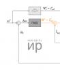
Tester for play in steering and suspension joints of vehicles with axle loads up to 4 tons. Model TL 200 is a permanently installed platform consisting of a fixed plate with anti-friction linings and a movable platform moved around an angular axis by a pneumatic cylinder rod. Pneumatic cylinder from the Italian company PNEUMAX. Controlling the movement of the platform using a button on the backlight of the inspected mechanisms. The platform is flat and does not require deepening. Installed on an inspection ditch or lift and secured with two screws.
2. Backlash measuring device ISL-401

The ISL-401 backlash meter is the only backlash meter adopted by Order of the Ministry of Internal Affairs of Russia No. 264 dated March 23, 2002 for the supply of internal affairs bodies of the Russian Federation and internal troops of the Ministry of Internal Affairs of Russia. The ISL-401 device is designed to measure the total steering play of vehicles by measuring the angle of rotation of the steering wheel relative to the beginning of the turn of the steered wheels in accordance with GOST R 51709-2001.
The total friction force in the steering is checked with the front wheels fully suspended by applying force to the dynamometer handles. Measurements are taken with the wheels in a straight position and in the positions of their maximum rotation to the right and left. In a correctly adjusted steering mechanism, the steering wheel should turn freely from the middle position (to drive straight) with a force of 8-16 N.
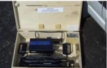
Currently, to determine the total friction force in steering, the use of electronic dynamometers, the general view of which is shown in the figure, is promising.
A qualitative method of visual assessment is used to make a conclusion about the condition of the steering rod joints (by touch at the moment of sudden application of force to the steering wheel or directly to the joints). In this case, the play in the hinges will manifest itself as mutual relative movement of the connected steering rods and impacts in the hinges. You can more accurately determine the play in the hinges connecting the steering rods using various play meters, for example, the one shown in the figure.
Steering Maintenance
car repair steering control
At EO Using a qualitative method of visual assessment and while the vehicle is moving, the following are checked: the tightness of connections and hoses of the power steering system, the free play of the steering wheel, the condition of the steering mechanism and steering gear.
At TO-1 check: fastening and cotter pins of the nuts of the steering axle levers, nuts and ball pins of the longitudinal and transverse steering rods; condition of the ball pin seals (detected faults are eliminated); fastenings (if necessary, secure the steering bipod to the shaft); steering gear housing on the frame and the locknut of the steering bipod shaft adjusting screw, free play and turning force of the steering wheel, play in the steering joints (if necessary, play is eliminated); tightening (if necessary, tighten the wedges of the steering gear driveshaft), tensioning the drive belts of the power steering pump (correct if necessary).
At TO-2 check the fastening and, if necessary, secure the steering wheel on the shaft and the steering column on the cab panel, remove and wash the power steering pump filter.
POSSIBLE MALFUNCTIONS, THEIR CAUSES AND REMEDY METHODS
|
Cause of malfunction |
Elimination method |
|
Increased free play of the steering wheel |
|
|
1. Loosening the steering gear housing bolts |
1. Tighten the nuts |
|
2. Loosening the tie rod ball pin nuts |
2. Check and tighten the nuts |
|
3. Increased clearance in ball joints. |
3. Replace tie rod ends or tie rods |
|
4. Increased clearance in the front wheel hub bearings |
4. Adjust the gap |
|
5. Increased clearance in the engagement of the roller with the worm |
5. Adjust the gap |
|
6. There is too much clearance between the swingarm shaft and the bushings. |
6. Replace bushings or bracket assembly |
|
7. Increased clearance in worm bearings |
7. Adjust the gap |
|
Stiff steering wheel rotation |
|
|
1. Deformation of steering gear parts |
1. Replace deformed parts |
|
2. Incorrect alignment of front wheel angles |
2. Check the wheel alignment angles and adjust |
|
3. The gap in the engagement of the roller with the worm is broken |
3.Adjust the gap |
|
4. The adjusting nut of the pendulum arm axis is overtightened |
|
|
5. Low pressure in front tires |
5. Set normal pressure |
|
6. Damage to ball joint parts |
6. Check and replace damaged parts |
|
7. There is no oil in the steering gear housing |
7. Check and top up. Replace the oil seal if necessary. |
|
8. Damage to the bearings of the upper steering shaft |
8. Replace bearings |
|
Noise (knocking) in the steering |
|
|
1. Increased clearance in the front wheel hub bearings |
1.Adjust the gap |
|
2. Loosening the steering ball pin nuts |
2. Check and tighten the nuts |
|
3. Increased clearance between the axis of the pendulum arm and the bushings |
3. Replace the bushings or bracket assembly |
|
4. The adjusting nut of the pendulum arm axis is loose |
4. Adjust the nut tightening |
|
5. The clearance in the engagement of the roller with the worm or in the worm bearings is broken |
5. Adjust the gap |
|
6. Increased clearance in ball joints of steering rods |
6. Replace tie rod ends or tie rods |
|
7. Loosening the bolts securing the steering gear housing or the pendulum arm bracket |
7. Check and tighten the bolt nuts |
|
8. Loosening the nuts securing the swing arms |
8. Tighten the nuts |
|
9. Loosening the steering intermediate shaft bolts |
9. Tighten the bolt nuts |
|
Self-excited angular oscillation of the front wheels |
|
|
1. Tire pressure is not correct |
|
|
2. Check and adjust the front wheel alignment angles |
|
|
3. Increased clearance in the front wheel hub bearings |
3.Adjust the gap |
|
4. Wheel imbalance |
4. Balance the wheels |
|
5. Loosening the tie rod ball pin nuts |
5. Check and tighten the nuts |
|
6. Loosening the bolts securing the steering gear housing or the pendulum arm bracket |
6. Check and tighten the bolt nuts |
|
7. The gap in the engagement of the roller with the worm is broken |
7. Adjust the gap |
|
Steering the vehicle away from straight-line motion in one direction |
|
|
1 . Uneven tire pressure |
1 . Check and set normal pressure |
|
2. The angles of the front wheels are violated |
2. Check and adjust wheel alignment |
|
3. Different draft of front suspension springs |
3. Replace unusable springs |
|
4. Steering knuckles or suspension arms are deformed |
4. Check the fists and levers, replace unusable parts |
|
5. Incomplete release of the brakes on one or more wheels |
5. Check the condition of the brake system, correct the fault |
|
Vehicle instability |
|
|
1. The alignment angles of the front wheels are violated |
1. Check and adjust wheel alignment |
|
2. Increased clearance in front wheel bearings |
2. Adjust the gap |
|
3. Loosening the tie rod ball pin nuts |
3. Check and tighten the nuts |
|
4. Too much play in the steering rod ball joints |
4. Replace tie rod ends or tie rods |
|
5. Loosening the bolts securing the steering gear housing or the pendulum arm bracket |
5. Check and tighten the bolt nuts |
|
6. Increased clearance between the roller and worm |
6. Adjust the gap |
|
7. Steering knuckles or suspension arms are deformed |
7. Check the knuckles and levers; replace deformed parts |
|
Oil leak from crankcase |
|
|
1. Wear of the bipod or worm shaft seal |
1. Replace the oil seal |
|
2. Loosening the bolts securing the steering gear housing covers |
2. Tighten the bolts |
|
3. Damage to sealing gaskets |
3. Replace gaskets |