Disc offset 40 and 45. About disc offset - permissible deviations
What do wheel rim parameters mean? Et40 what is it
|
||||||||||
website
What do wheel rim parameters mean? ― Thomason Russia
You can find markings on almost every car wheel. If you find one, then, having read the symbols below, you can easily understand all the information you need related to this product, which will allow you to determine the degree of its compliance with your car.
However, before you start selecting car rims yourself, we recommend that you look at the owner’s manual for your car. Here you will find the parameters required and recommended by the manufacturer of your vehicle. It should be remembered that automakers calculate suspension elements, braking systems, wheel fastenings, etc. for certain types of wheel rims.
Another way to find out the necessary indexes is to read the markings from the disks currently installed on your car.
Decoding the markings of wheels for cars
Let's look at the markings of a car wheel using the following entry as an example:
6.5 J x 15 h3 5x100 ET45 d54.1
6.5 (rim width) – rim width A, measured in inches.
15 (rim diameter) – wheel rim diameter B, measured in inches. This value is determined without taking into account the height of the rim edges.
J (flange) – designation of the flange profile of the F rim. J is the most common type. Also for passenger car rims there are the following types: JJ, JK, K, B, D, P.
h3 (hump) – ring protrusions H on the rim seat. Humps are designed to reliably fix the beads of tubeless tires during lateral impacts, such as when cornering, preventing the outflow of air. The h3 index means that such protrusions are present on both sides of the rim (in contrast to the H index, which indicates the presence of a hump on only one side).
d54.1 (hub diameter) – the diameter of the central hole D for the wheel hub (DIA), which is measured from the side of the mating plane. DIA is one of the most important indicators that determine the suitability of a wheel rim for a vehicle. Exact matching of the diameters of the landing cylinder and the disc hole ensures absolute centering of the wheel. If these diameters do not coincide, then final centering is ensured by means of conical or spherical shapes at the mounting bolts/nuts and the corresponding holes of the auto disk. Also in this situation, centering rings are used.
As a rule, an accurate fit is ensured when installing original car manufacturer rims. Most third-party wheel rims are equipped with sealing centering rings. This is due to factors such as the relative unification of disks and the reduction in the cost of their production - it is significantly cheaper to supply products with centering rings than to produce products that differ only in the diameter of the central hole in fractions of a millimeter.
Location of mounting holes
5x100 – number N of holes for mounting bolts/nuts (5) and diameter C of their location (100mm). The diameter of the circle around which the holes are placed is called PCD (Pitch Circle Diameter).
Depending on the number of mounting holes, different coefficients are used to calculate the PCD parameter from the known distance between holes (see figure below).
The fastening holes may have a decent tolerance in diameter, but the bolt fits unambiguously and absolutely in the center due to conical guides. Therefore, the minimal discrepancy between the centers of the holes at the disk and the hub means that a tight fit is ensured by only one bolt - the rest, most likely, will be tightened skewed, excluding correct centralization. Thus, when the wheel rotates, we will have runout - this time, and the second - an additional “rotating” load on the bolts or nuts.
IMPORTANT!
Installation of car wheels with a PCD other than the nominal one is prohibited!
What could lead to a deviation of this parameter from the specified one? A delta of a couple of millimeters, which is not noticeable to the eye and does not seem to affect driving performance, can cause the disc mounting bolts to loosen from the hubs while driving.
If you have any doubts or difficulties when selecting a wheel for your car, in order to avoid any incidents, it is better to entrust this task to a consultant in our online store.
ET45 (Einpress Tief, German; offset, English) – disk offset E: the distance between the wheel disk mounting plane and the rim symmetry plane, mm. For each vehicle, this parameter is set by the manufacturer.
As the ET value decreases along the numerical coordinate axis, the wheels begin to protrude to the sides beyond the car body - the track becomes wider. Increasing the offset leads to a narrowing of the track. Typically, the delta allowed by the manufacturer is about ½ cm.
The ET parameter is optional and may not be included in the disk labeling.
IMPORTANT!
By adhering to the recommended values, you ensure a safe position of the wheel in the wheel arch and optimal load on the suspension and steering mechanism.
Increasing the disc offset is unacceptable - this can lead to mechanical contact between the disc and the brake system elements. Reducing the offset, although it allows you to achieve slightly greater stability of the car, as well as the dubious pleasure of “hanging out nicely,” but entails an increase in the shoulder and, as a result, overloading the mechanics of the hub and suspension.
Install wheels with offsets other than those recommended at your own risk!
X-factor is a very arbitrary X indicator that determines the distance between the wheel rim mounting plane and its rear surface. This space itself allows you to install discs on cars in which elements of the brake system protrude beyond the mating plane.
www.tomason-russia.ru
ET40 is... What is ET40?
ET40 is a two-section DC electric freight locomotive built in Czechoslovakia at the Skoda plant in Pilsen specifically for export to the People's Republic of Poland to the Polish State Railways (PKP).
In Poland, these electric locomotives were operated with coal routes on the Coal Main Line (Polish: Magistrala węglowa) between the coal deposits in Upper Silesia and the port city of Gdynia.
In the 1960s and 1970s, rail transport in Poland increased. Their growth was especially large along the line connecting the Upper Silesian coal basin and ports on the Baltic Sea. In the early 1970s, the main railway line leading in this direction - the coal main line - was electrified with direct current (3 kV). To service the electrified line, relatively powerful electric freight locomotives capable of hauling heavy freight trains were required.
After negotiations, an order for a batch of 60 such locomotives was placed in Czechoslovakia at the Skoda plant. Their design was based on the design of the EU05 electric locomotive, which was supplied to the socialist countries as a passenger locomotive (in the USSR this electric locomotive was designated the ChS3 series).
The electric locomotive was combined into two sections, the second cabins were eliminated, and other changes were made to the design. The factory designation of this series of electric locomotives is 77E1 (30 units manufactured in 1975) and 77E2 (30 units manufactured in 1978).
Since 2007, ET40 electric locomotives have been transferred to the Bydgoszcz locomotive depot, but several machines have been in operation on the Wroclaw - Jelenia Góra line since 2000, replacing outdated ET21 electric locomotives there.
The main differences between the ET40 electric locomotive and its predecessor are related to changes in the control circuits, power circuit, traction drive and cooling system. Each section of the locomotive has a driver's cabin at one end and a vestibule for access to the adjacent section at the other end.
Under each section there are two two-axle trolleys. All wheel sets of the electric locomotive have an individual traction drive through a cardan shaft. The gear ratio is 84:27. Traction motors 7AL-484ZT with a continuous power of 510 kW are suspended on a trolley.
The entrance to the electric locomotive is carried out directly through the driver’s cabin, both on the left and on the right side. The driver's cabins are heated with electric heaters. The cabins have household refrigerators for storing food. The window wipers are electrically driven. On the rear wall of the driver's cabin there is a wardrobe for outerwear of members of the locomotive crew, as well as a door that provides access to the terminal strips. There are two doors leading from the driver's cab - one into the passage corridor, the second goes directly into the high-voltage chamber.
The total length of the electric locomotive is 34420 mm, the diameter of the wheel sets with moderately worn tires is 1250 mm.
The electric locomotive is equipped with electro-pneumatic additional loaders for the front wheelsets in the direction of travel.
Braking system - automatic Oerlikon brake and direct acting.
Electric locomotives from 01 to 30 had one current collector per section, and from 31 to 60 two.
Traction motors on the series connection had a terminal voltage of 1500 volts. The engines of one cart are cooled by one fan motor. Each section has one short-term-repeated air compressor with a capacity of 140 cubic meters per hour.
Polish railway workers nicknamed the electric locomotive “Bombovoz” or “Bomb”.
Offset is the most important geometric parameter of a wheel rim. And this is by no means an exaggeration. We will try to explain the reason for this, as they say, with our fingers. So, if a car wheel does not fit in diameter, the number of holes for mounting bolts, or the interval between these holes, then it simply cannot be put on the hub. But usually such discrepancies with the standard (declared by the car manufacturer) offset are not very large, which makes installation possible without difficulties. Will the wheel fulfill its role one hundred percent in this case? And if not, then what will such an experiment lead to? On the Internet on thematic websites, vehicle owners often discuss the topic of how much the offset of the installed disc can differ from the recommended one, and if this discrepancy is acceptable, then in what direction? Often the points of view expressed have diametrically opposite directions.
As for the distributors of car wheels, be it a specialty store or a car market, in nine out of ten cases they will say that a small deviation of the offset from the standard parameters is acceptable. And they will certainly add that if the assembled wheel is easily mounted on the hub, without catching or touching either the body or the suspension during rotation, then it can be used without any doubts or risks. Moreover, people trading will assure that reducing the size of the departure, regardless of the recommended parameters, is not a problem at all and does not pose any danger. All this is easily explained by their desire to quickly sell their goods, and often by banal ignorance. But how are things in reality? Let's start with the basics.
How to determine disc offset?
Disc offset is the distance from the central axis of the disc to the plane of attachment to the hub. Determining it is elementary, because there is a simple formula that looks like this:
ET=X-Y/2(calculated in millimeters)
- ET – required value (offset).
- Y – width of the rim itself (total).
- X is the distance between the plane of application of the disk to the hub and its internal plane.
 Obviously, the resulting number can be either with “+” (the most likely option), or with “-“, or even go to zero. An important point is the fact that offset directly determines the width of the wheelbase, since it forms the interval between the centers of the wheels located on the same axle. Analysis of the formula also shows that it is not affected by either the disc diameter, width, or tire dimensions.
Car suspension loads are calculated based solely on the force application arm, which is the distance from the hub to the center of the wheel. This means that there can be only one wheel offset required for a particular car model. Regardless of the tire size and the size of the wheels themselves.
The offset value is indicated on the surface of each disc. This is the ETxx marker, where xx is the distance in millimeters. It, as already mentioned, can be zero (ET0), positive (ET35) or negative (ET-35)
Are disc offset deviations allowed?
No matter how convincing the salesperson's arguments, you must clearly understand the fact that the offset of the purchased disc must coincide 100% with the vehicle manufacturer's instructions. In no case are the slightest deviations in any direction allowed. It is very simple to explain such a categorical statement. Even with a tiny discrepancy in values, the operating conditions of absolutely all suspension elements without exception change automatically. In this case, forces arise for which these nodes are not designed. In addition, the vectors of application of these forces change, which is also not provided for by the chassis design. As a result, the service life of the mechanisms is significantly reduced, and when critical loads occur, the suspension units may completely collapse, which is very dangerous to life. 
Statements by CD sellers about a variety of options and nuances are just an attempt to sell you any product, in the absence of one that is ideally suited to your needs. Words about possible permissible deviations significantly expand the offered range of discs, and therefore increase the opportunity to earn money. No more.
Different configurations of one car model
Some car enthusiasts have noticed that different parts for different versions of the same car model are often used. This is due to the fact that when designing and calculating the parameters of components of each modification, a huge number of variables are taken into account, which can differ markedly for cars of the same line. An example of this is various power plants having different dimensions and weight. According to these calculations, taking into account in each case the acting forces and vectors of their application, the final suspension design is formed. This allows us to guarantee the client reliability, ride comfort, high-quality handling and other characteristics, with minimal production costs.
In the old days, most vehicle manufacturers manufactured parts in such a way as to provide a large margin of safety in the main structures of the car, including the suspension. Today, the trend in the market is such that there is a demand for reducing the cost of transport, which is achieved through more accurate calculations. This resulted in a decrease in the safety margin of most parts.
Forces acting on suspension elements
Absolutely any element of the suspension is subject to several multidirectional forces. And it is quite natural that this list increases with the complexity of the design, which is very different from modern machines. Therefore, we offer for consideration the simplest example, where the hub is attached to the body by means of a lever and a strut with a shock absorber (MacPherson system).
 The force exerted on the wheels is directed upward from the plane along which the car is moving, and the mass of the car is distributed between all wheels. In this case, the points of application of these forces are the centers of the tire contact patch area. And if we assume that the suspension and camber angles are in ideal condition, and the wheels are well balanced, then these centers will be located on the axis of symmetry of each wheel. It is in this place that the axis of the shock absorber strut should fall.
Everything else is simple. The acting force corresponds to the proportion of the car's mass attributable to the wheel. It is directed away from the ground and creates moments in the levers, wheel bearing, and struts with shock absorbers. In the first two cases it will be tension, and in the last case it will be compression. All these points are carefully calculated at the design and construction stage. Naturally, a safety margin is provided for each part, but it was already mentioned above that it is constantly decreasing due to the widespread desire to reduce production costs.
When the calculated offset changes, the forces change their magnitude and direction, because a decrease in offset expands the wheelbase, and an increase - narrows it. This entails a displacement of the steering axis and a change in the parameters of steering wheel rotation, moments of forces and vectors of their application. This aspect also negatively affects the wear resistance of tires, maneuverability and controllability of the vehicle. Taken together, all of these factors lead to the fact that the suspension is operated in a mode that was not intended by the automaker. The level of driving safety decreases, and the service life of most structural elements decreases sharply.
In conclusion, let's say the following. If a new wheel with an offset that does not coincide with the standard one easily fits on the hub of your car, this is not a reason to use it without fear. It cannot be said that the operation of vehicles in such equipment will be safe. Wheel spacers can be a solution, but only if the offset is greater than standard, and you were able to find suitable spacers, which is often very problematic.
Disc overhang is the distance from mating plane disk (the plane by which the disk comes into contact with the plane of the hub when mounting the wheel on a car) to the center line, which divides the disk into two symmetrical halves (and is parallel to the mating plane).
Disc offset marking
The offset value (the distance between the planes) is measured in millimeters, and in the coding applied to the inner surface of the disk, where all the parameters of the model are displayed, the offset is marked with the designation ET (in some cases DEPORT, OFFSET).

Types of disc ejection
Considering the huge number of car models, wheel manufacturers offer a fairly wide range, which includes wheels with different offset values. There are three types of disc ejection:
Zero departure- the mating plane of the disk coincides with the central plane of the wheel;
Positive departure- the mating plane of the disk is located behind the central plane of the wheel;
Negative departure- the mating plane of the disk is located in front of the central plane of the wheel.

Depending on the type of departure, the marking may look like this: ET20 (positive), ET0 (zero), ET-20 (negative).
Disk ejection parameters strictly regulated by the plant manufacturer, and these parameters must correspond to the overhang values indicated on the disc label. Due to discrepancies in the offset parameters, the wheel may touch body elements when moving (negative offset) or come into contact with suspension elements (positive offset).
In addition, the importance of compliance of this parameter with the recommendations of the vehicle manufacturer is enhanced by its non-obviousness. That is, if, if the diameter and number of mounting holes do not match, the wheel simply cannot be installed, then if the offset values do not match, the disk can “fit” perfectly onto the hub.
However, as a result of a discrepancy between the offset parameter and the “standard” parameters, significant loads may occur on the suspension, which is not designed to operate under such loads. And this causes premature failure of the suspension, and therefore the use of such a disc is no longer safe. In addition, the discrepancy between the reach affects the car's handling, the predictability of cornering behavior decreases, the steering wheel becomes less easy to rotate, and uneven tire wear appears.
Car owners' needs
However, car enthusiasts have installed and continue to install wheels with inappropriate offset. This persistent desire is mainly due to simple ignorance of the subject or the need to “pump up” your car, as well as install wheels that, although not very suitable according to factory recommendations, nevertheless look very impressive.
Car owners often use offset deviations in order to enhance the performance characteristics of the vehicle. The smaller the offset relative to the axle, the more the wheelbase expands, resulting in increased stability and controllability of the car. In addition, the extended base gives the car a more sporty appearance, which is why the appearance undoubtedly benefits.
The use of discs with offset deviations is also determined by the assortment of the market - the choice of models presented by sellers. Thus, wonderful wheels that ideally suit the car in terms of aesthetic characteristics have only a slight deviation from the recommended parameters. For some car owners, this is sufficient reason to prefer this model to wheels that are less interesting, but ideally suited to a particular car in terms of its parameters.
However, there is a way to bring the disc offset in accordance with the requirements of the car manufacturer - the use of wheel spacers; this method will be discussed in more detail below. Now let's look at the following questions:
- Why are manufacturers not inclined to allow offsets to differ from standard indicators?
- Why do car owners and wheel sellers allow the possibility of using wheels whose offset does not fully comply with the recommendations;
- What forces act on the suspension, and what exactly happens when the offset changes.
Matching the needs of the car enthusiast and the capabilities of the manufacturer
The question of how much deviation from the automaker's recommendations is acceptable is actually quite controversial. Many manufacturers insist on full compliance, some completely allow the offset to be within +/- 5mm, and there are models for which the recommended offset varies depending on the modification. What is the reason for the manufacturer’s desire to prevent deviations from the recommended parameters?
Just a couple of decades ago, when designing cars, a significant margin of safety was laid down, which allowed the components and assemblies of cars to withstand some overloads without noticeable damage. Today, the level of strength of materials, the choice of technologies with which these parts are made, and, accordingly, the final price of the car depend on the accuracy of calculations of the loads to which car parts are exposed.
In conditions of fierce competition, automakers are forced to save money in order to increase the price attractiveness of their models, so the loads on all elements are calculated very accurately, and even a relatively small discrepancy with the recommended parameters can lead to an increase in the load, and, accordingly, to part failure. It is calculated that if the disc offset is reduced by 50 mm, this leads to an increase in load by one and a half times. Naturally, such a discrepancy leads to rapid failure of the suspension.
This also explains the different reach for cars of the same model, but equipped with different engines. The weight of the engines differs; accordingly, the load on the suspension will be different; the forces and vectors of their application change. However, in such cases, the difference in the recommended offset value rarely exceeds +/- 5mm.
Disc sellers, in turn, are in no hurry to assure their customers of the need to strictly follow the recommendations of automakers, and there is also a reason for this.
- Firstly, among the abundance of models, it is quite difficult for a car owner to find a set of wheels whose parameters ideally correspond to the recommendations of the car manufacturer. That is, the car owner has to sacrifice something, purchasing less beautiful wheels or wheels of the most advantageous configuration, but not fully meeting the offset requirements;
- Secondly, a discrepancy of a few millimeters actually only minimally increases the load on the suspension. It is difficult to imagine that one or two millimeters could cause serious overloads;
- Thirdly, the use of wheel spacers allows you to level out discrepancies, minimizing possible harm to the suspension and tires.
Therefore, a small deviation in reach is still acceptable, which is what the masters of tuning companies and “advanced” car owners who strive to maximally improve the performance of their cars take advantage of. The maximum permissible deviation in most cases is +/- 5mm, but for some models even this is too large a deviation. Therefore, the best option would be to strictly follow the manufacturer's recommendations, which would be guaranteed to help avoid problems with the suspension (as a result of changes in offset).
How to measure disc offset yourself
You can measure the ET (disc offset) parameter yourself; for this you will need the following tools:
- Rake (recommended length corresponds to the radius of the disk);
- Measuring tool (ruler or tape measure);
- Jack (for removing the wheel);
- Balloon wrench (key for security bolts);
- Tackles.
First, we measure the rear offset (A), also called BACK SPACING, for this you need to place the wheel face down, place a rack on the inside of the rim, and the ends of the rack should lie on the rim of the rim (not on the rubber or the inside of the rim). We measure the distance from the disk to the edge of the rail (bottom), measurements are taken in millimeters.

Then you need to measure the front setback (B), to do this you need to place the wheel face up, and place the rack so that its edges lie on the rim (not on the spokes or other structural elements). We measure the distance from the mating plane of the disk to the edge of the rail (bottom).

After the measurements have been taken, it is necessary to calculate the offset (ET, in millimeters) using the following formula:
ET = (A+B)/2 - B
where A is the rear indentation, and B is the front indentation.
So, if our dimensions had the following values:
A is 153mm, and B is 53mm, then the offset value (ET) = (153+53)/2 - 53 = 50 mm.
A little about the forces acting on the suspension
The mass of the car is evenly distributed between the four wheels, and the force that acts on each wheel is directed from the road surface. The point of application of force is the center of the contact patch; during movement, this center is located along the line of symmetry of the wheel. Accordingly, the axis of the shock absorber strut should also be directed towards this center line. The force acts through the center of the contact patch on the strut with the shock absorber, on the lever and on the step bearing, tie rod ends, and when designing the car, the intensity of its influence is taken into account.

The offset determines the location of the central axis relative to the hub, and if the central axis moves (when the offset changes), then the steering axis moves along with it, and the force application vector changes. At the same time, the rotation parameters of the steering wheel change, making it difficult to perform maneuvers, the contact patch when turning changes, which leads to uneven wear of the rubber. Accordingly, the suspension no longer operates in the mode that was calculated when designing the car, and its elements quickly fail.
Wheel spacers
As already mentioned, the use of wheel spacers is a way to reduce the offset to the standard value. Spacers are flat metal pancakes that are installed between the disk and the hub and act as a kind of spacers. Thus, if a car enthusiast has his eye on wheels that meet all the parameters (width, diameter, centering hole, number and diameter of the axle placement of bolt holes), except for the offset value, he can easily use these wheels by installing wheel spacers of the required thickness.
Wheel spacers are used not only to bring the offset value into line with the recommended parameters, but also to change it in one direction or another (extending the wheelbase during tuning), or in the event that the number and location of the holes for the hub bolts does not match the disk .

There are two main types of wheel spacers:
- The first ones have through holes and a thickness of 6 - 12 mm; to install them, you need to select bolts that are longer than the standard ones by the thickness of the spacer;
- The second (thickness 12 - 20mm) have holes for the hub bolts, as well as separately for the bolts that secure the gasket to the disk. That is, such spacers can be used if the mounting holes on the disk (size, number, distance) do not match the holes on the hub. In addition, spacers of this type have an additional centering hole, and when purchasing, you need to make sure that this hole coincides with the centering hole of the disk.
There is also a difference between the ways to use wheel spacers:
- Bringing departure parameters to standard values;
- Adaptation of the disk to the hub (if the mounting holes do not match);
- Change in offset relative to the standard value (widening or narrowing of the wheelbase).
The feasibility of using spacers directly depends on their quality, as well as the method of use. Thus, poor-quality wheel spacers (errors in the dimensions of the mounting holes, unsuitable metal) can cause a sudden accident or contribute to the rapid failure of the suspension. If we are talking about intentional changes in departure relative to standard parameters, then the consequences that such modifications can lead to were discussed above.
X-factor (Caliper Clearance or Brake Clearance)
An additional parameter that should be taken into account when choosing wheel rims is the X-factor - the distance between the mating plane (the plane where the disk is attached to the hub) and the inner surface of the front side of the disk (its spokes). This parameter depends on the disk configuration (stamping shape, casting, spoke bending) and affects the possibility of installing disks on a car whose brake elements protrude beyond the mating plane.

If the disc model has an X-factor value approaching zero, then these discs are not intended for cars whose brake system design requires protruding brake elements. The rims are only suitable for vehicles without protruding elements. And if the X-factor value is sufficient, then the disk can be installed on any car (of course, provided that the other parameters of the disk correspond to the parameters of the car).
Thus, wheels that correspond to the car model in all respects reflected in the marking may not be suitable for a car of a certain brand. There are two ways to find out whether the disks will fit or not.
- The first method is to try on the disc before starting beading before installation;
- The second way is to search for compatibility catalogs, which many wheel manufacturers post on their official resources on the Internet. If the catalog indicates that the disc is suitable for a car of a certain model, then you can safely order a set, the discs are guaranteed to “fit” onto the hubs.
However, there is a way to change this parameter using the same wheel spacers. It should be taken into account that with a change in the value of the X-factor, the departure will also change (and exactly as much as the X-factor has changed). Therefore, it is better to choose a disk model in such a way that, with the installation of a spacer, the offset is compensated to the standard value.
Disc offset, or as it is commonly referred to as ET, is one of its most important parameters, showing the distance between the area where the wheel rim is adjacent to the hub and its vertical plane, which is responsible for symmetry. Thanks to this parameter, the car enthusiast can immediately understand whether the wheel will fit on his iron horse or not. But we will try to look at the example of disk offset 40 and 45 (what is the difference, possible deviations, etc.) in the article below.
How to calculate the indicator using the formula?
As mentioned earlier, by the ET indicator you can determine whether the selected “sneakers” will fit on the car or not. And this procedure is carried out according to the following formula: ET=A-B\2, where:
- A – the distance from the inner surface of the wheel rim to the area of its contact with the hub (indicated in mm);
- B – rim width.
The result can have three parameters: good, zero and bad. With the first result, there will be a small gap between the area where the wheel touches and the hubs themselves, which means that such a wheel will be ideal for this vehicle.
If the calculation according to the formula showed a zero result, then, in principle, such “sneakers” can also be installed on a car. But, in this case, the above-mentioned clearance between it and the hubs will not be observed, which will significantly increase the load from the impacts received (if the wheel falls into a hole, or hits an uneven surface). But with a negative projection, the wheel cannot even be installed on the car, since the hubs simply will not allow it to fit under the wheel arch.
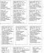
Permissible deviations
We have already looked at what a protrusion is and how it is calculated. And before moving on to the question of what is the difference between the ribs ET 40 and ET 45, let's consider in advance the permissible deviations of this indicator in the table below:
Secondly, the vehicle will have visual differences. Namely: when installing the ET 40 rim, the wheels will practically not stick out from under the arches of the car, while the ET 45 will make them stick out as much as 5 mm, which will be visually very noticeable. But, unfortunately, it will not be possible to unanimously assert that such a change will be negative. After all, some car enthusiasts specifically choose wheels with a large protrusion (within the permitted limits) so that the wheelbase of the car appears wider. Otherwise, there will be no difference between disc offset 40 and 45. This means that you can safely install both options on your machine without fear of any consequences.
Expert opinion
Despite the fact that a 5 mm deviation of the protrusion is not considered significant, car manufacturers persistently do not recommend that motorists install such “sneakers” on their iron horse. And they argue this by saying that with a changed rim offset (different from that recommended by the manufacturer), the technical and dynamic qualities of the vehicle change significantly. Well, in addition to this negative phenomenon there is also a reduced service life of the part, which does not correspond to the warranty.
But sellers have a completely opposite opinion on this matter. And they explain it by saying that it is very difficult to select a specific disc with an offset. But given acceptable deviations, the range of shoes for cars increases significantly, which benefits both buyers and sellers. Well, you can decide for yourself which ledge is suitable for your iron horse, based on the information provided above.
Disc offset is one of the most important geometric characteristics, along with the diameter and number of bolted connections. Although there is still a slight discrepancy from the requirements that the company that manufactures and produces the car insists on.
To correctly measure the distance between the vertical (vertical) plane of symmetry of the wheel and the very surface of the disk to the car hub in mm, you need to use the formula:
ET=a-b/2, where
a – span between two verticals, the inner plane, and the surface adjacent to the hub
b – the entire width of the car rim.
To put it in ordinary, understandable words, the offset of an ET disc is an indicator of how much it looks outward from the wheel arch. If the offset is large, then the wheel will retreat deeper, and if its indicator decreases, on the contrary, it will move outward.
WATCH THE VIDEO
- Null;
- Negative;
- Positive.
This value is often applied to the inner surface of any car rim, and their unit of measurement is expressed in mm. Other parameters of the disks are also included; they mean the following:
- Width;
- Diameter;
- PCD of the disk - the number of fastening bolts and the diameter of their location;
- DIA - diameter of the mounting hole located in the center;
Minus or negative offset
Naturally, this has a characteristic effect on the steering characteristics, and therefore on the maneuverability of the car as a whole. The vectors and moments of force directly affecting various suspension elements change. All this will undoubtedly force the entire chassis of the car to work in a different mode, which is absolutely not taken into account by the manufacturer, so when purchasing wheels with a negative offset, it is better to consult with a manager or a store specialist.
Large offset (15,35,40,45) and its increase using a spacer
The suspension of a truck or car is clearly standardized and calculated by the manufacturer and the designers developing it. However, if you approach this tuning wisely, then in the end the increased wheelbase of the car and its track can increase the stability of the car.
And also the wheels protruding beyond the edges of the car will be a plus when supplementing it with plastic modifiers. The main thing that a car enthusiast needs to clearly understand is that the service life for which a given wheel bearing is designed decreases in direct proportion to the difference in the distance of the displaced disk and the original one recommended by the manufacturer.
To increase the disc overhang, a so-called spacer element is used. It is installed tightly between the disc and the drum, or the hub, it all depends on the model and design of the car’s brakes. The dimensions of these elements are of great importance; there are several types:
- Thickness up to 6 mm is considered small, but often the length of the original mounting bolt is enough to properly fix the disc together with the iron spacer.
- Thickness up to 25 mm. they already have a centering hub, which eliminates the option of destabilizing the balancing of the wheel parameter. The car acquires notes of a sporty, aggressive character and the spacers installed on it are visually identified.
- The thickness of the spacer is from 25 to 50 mm, which is considered quite large. They are attached to the hub or drum not only with bolts, but also with studs. Bolts are recommended for VAZ cars, fastening with a stud for brands such as Niva or UAZ.
The spacer to increase the offset must be made of durable metal. Therefore, before a car enthusiast starts making them manually, it is worth considering the risks and consequences of their installation. Still, it is recommended by experts to purchase high-quality factory spacers and offset wheels, which will be made from the required grade of steel, and also meet all reliability and safety requirements. Naturally, when choosing and specifying the parameters of disks and spacers, it is worth taking into account the number of mounting bolts and their length.
The influence of wheel width and offset ET on driving characteristics
Every car owner who is thinking about installing a disc with a non-standard offset should think about the consequences, and in particular, what can happen after their installation, as well as what exactly the disc offset affects:
- Steering axis offset;
- Sudden wear of bearings ahead of schedule;
- A radical change from the previous factory handling;
- Changing the service life of tires and all suspension parts and components.
All these reasons are not just words; they are based on the laws of physics. After all, it is known that the mass of any four-wheeled mechanism is generally distributed over all its wheels. The point of application of force is directed at the base of contact of the road surface directly with the wheel.
Even if we assume theoretically that the chassis and suspension are absolutely in good working order, then the vector of the wheel axis will be laid through this base. The vector line of the car's shock absorber located in the strut is also directed to the same point.
Installing wheels with an offset offset will change the vector of these forces, and therefore their load. That is, the installation of non-regulatory wheels will change the appearance of the car, making it unique and inimitable, but the driving performance will deteriorate, and the wear of spare parts will increase significantly. Of course, if the manufacturer does not provide for such a replacement.
Acceptable table of deviations for the most common car brands (Mercedes, Toyota, UAZ)
Each specific car brand has its own permissible deviations, which are best not violated.
| No. | Automobile model | Allowable disc overhang, mm |
| 1 | Chevrolet Camaro | 38-50 |
| 2 | Chevrolet Corvette | 38-50 |
| 3 | Chevrolet Aveo 1.6 | 39 |
| 4 | Alfa Romeo 33 | 30-38 |
| 5 | Alfa Romeo GTV | 28 |
| 6 | Alfa Romeo 145 | 38 |
| 7 | Alfa Romeo 146 | 38 |
| 8 | Alfa Romeo 166 | 35-40 |
| 9 | Alfa Romeo 155 | 38 |
| 10 | Alfa Romeo 156 | 28-30 |
| 11 | Audi A4 | 35 |
| 12 | Audi A8 | 35 |
| 13 | Audi A6 | 35 |
| 14 | Audi 80 | 35-42 |
| 15 | Audi 100 | 35-42 |
| 16 | Audi TT | 28-30 |
| 17 | Audi Quattro | 35-42 |
| 18 | Audi A3 | 30-40 |
| 19 | BMW 3 | 15-25 |
| 20 | BMW 3 (E36) | 35-42 |
| 21 | BMW M3 | 18-20 |
| 22 | BMW 5 | 18-20 |
| 23 | BMW 7 | 18-20 |
| 24 | BMW 7 (E32) | 18-20 |
| 25 | BMW 8 | 18-20 |
| 26 | Citroen Berlingo | 15-22 |
| 27 | Citroen Jumper | 35 |
| 28 | Citroen Evasion | 28 – 30 |
| 29 | Citroen Xsara | 15 – 22 |
| 30 | Citroen Xantia | 15 – 22 |
| 31 | Daewoo Nexia | 38 – 42 |
| 32 | Daewoo Espero | 38 – 42 |
| 33 | Daewoo Lanos | 38 – 42 |
| 34 | Daewoo Matiz | 38 |
| 35 | Daewoo Leganza | 35 – 42 |
| 36 | Daewoo Nubira | 38 – 42 |
| 37 | Dodge Magnum 2.7 V6 | 24 |
| 38 | Dodge Avenger 2.0i | 35 – 39 |
| 39 | Dodge Caliber 2.0 | 35 |
| 40 | Dodge Caliber SRT4 2.4i | 40 |
| 41 | Dodge Caravan 2.4i | 35 – 40 |
| 42 | Dodge Challenger 6.1 V8 | 40 |
| 43 | Dodge Durango 3.7 V6 | 15 |
| 44 | Fiat Qubo 1.3 | 40-44 |
| 45 | Fiat Bravo 1.4i | 31 – 32 |
| 46 | Fiat Croma 2.2 | 35 – 41 |
| 47 | Fiat Doblo 1.9JTD 263 | 32 |
| 48 | Fiat Doblo 1.9JTD 223 | 32 |
| 49 | Ford Scorpio | 35 – 38 |
| 50 | Ford Cougar | 35 – 38 |
| 51 | Ford Explorer | 0 – 3 |
| 52 | Ford Escort | 35 – 38 |
| 53 | Ford Focus | 35 – 38 |
| 54 | Ford Focus 2 | 35 – 38 |
| 55 | Ford Fiesta | 35 – 38 |
| 56 | Ford Granada | 35 – 38 |
| 57 | Ford Galaxy | 42 – 45 |
| 58 | Ford Ka | 35 – 38 |
| 59 | Ford Mondeo 1 | 35 – 42 |
| 60 | Ford Mondeo 2 | 35 – 42 |
| 61 | Ford Mustang | 35 – 38 |
| 62 | Ford Sierra | 35 – 38 |
| 63 | Ford Scorpio | 35 – 38 |
| 64 | Ford Orion | 35 – 38 |
| 65 | Ford Puma | 35 – 38 |
| 66 | Ford Windstar | 35 – 38 |
| 67 | Ford Transit | 35 – 38 |
| 68 | Honda Shuttle | 35 – 38 |
| 69 | Honda CRX | 35 – 38 |
| 70 | Honda Accord | 35 – 38 |
| 71 | Honda Integra | 35 – 38 |
| 72 | Honda Civic | 35 – 38 |
| 73 | Honda Civic VTEC | 38 |
| 74 | Honda Concerto | 35 – 38 |
| 75 | Honda Jazz | 35 – 38 |
| 76 | Honda Prelude | 38 |
| 77 | Honda Legend | 35 – 38 |
| 78 | Honda CRV 5 | 40 – 45 |
| 79 | Hyundai Pony | 35 – 38 |
| 80 | Hyundai Accent | 35 – 38 |
| 81 | Hyundai Coupe | 35 – 38 |
| 82 | Hyundai Lantra | 35 – 38 |
| 83 | Hyundai Sonata | 35 – 38 |
| 84 | Hyundai Excel | 35 – 38 |
| 85 | Kia Shuma | 35 – 38 |
| 86 | Kia Ceed | 38 – 42 |
| 87 | Kia Leo | 35 – 38 |
| 88 | Kia Clarus | 35 – 38 |
| 89 | Kia Sephia | 35 – 38 |
| 90 | Kia Concord | 35 – 38 |
| 91 | Kia Sportage | 0 – 3 |
| 92 | Kia Mentor | 35 – 38 |
| 93 | Mercedes-Benz Sprinter | 45 |
| 94 | MercedesBenz A Class | 45 – 50 |
| 95 | MercedesBenz B-Class | 47 – 52 |
| 96 | MercedesBenz C-Class | 43 – 47 |
| 97 | MercedesBenz E-Class | 48 – 54 |
| 98 | MercedesBenz G-Class | 43, 50, 63 |
| 99 | MercedesBenz M-Class | 46 – 50, 60 |
| 100 | MercedesBenz S-Class | 36 – 43,5 |
| 101 | MercedesBenz SLK | 45 – 50 |
| 102 | MercedesBenz 600SL | 18 – 25 |
| 103 | MercedesBenz 280SL | 18 – 25 |
| 104 | MercedesBenz Vito | 45 – 50 |
| 105 | Mitsubishi Lancer | 35 – 42 |