Thermal relay 1209. Electronic thermostat W1209 from Aliexpress
To make a homemade incubator, I needed to purchase a temperature regulator. The requirements for it were: small dimensions, low cost, power supply from 12 V DC, a powerful executive relay (to withstand a significant load), indication of readings, setting parameters with control buttons, accuracy of temperature measurement and maintaining set parameters, and of course reliability.
On the Internet I came across such a device - . Reviews about it met my requirements. Came to me from the Aliexpress website. This regulator can be used in many places - electric heating, incubators, refrigerators, drying cabinets, water heating systems, protection of electrical equipment, measuring the temperature of a car's coolant and then turning on the fan in a greenhouse, bathhouses, heated floors, heating pipes, etc... The regulator itself consists of an electronic board with 3 control buttons installed: SET The SET button serves to select a mode and set parameters, and with the and buttons you can directly change the data of the programmable parameters. The LED indicator has three digits. The temperature meter itself is based on a thermometer installed in a case and has a wire length of 30 cm.
The control limits lie in the range from -50.0 to 110.0 degrees. You can connect loads up to 15 A (at 12 V DC) and up to 5 A (when powering the load from 220 V network)
The device is powered by 12 -14 V DC. The measurement accuracy is within 0.1 Celsius. The regulator current consumption is 35 mA when the relay is operating: 65 mA. In my article I will tell you how to set up and slightly upgrade this thermostat.
The process of setting up the W1209 thermostat is shown in the video:
List of tools and materials
-knife or scissors;
-screwdriver;
- soldering iron;
-tester;
- a plastic tube from ear sticks or a pen refill;
- faulty LEDs with a diameter of 5 mm - 4 pieces;
- plastic stands - 4 pcs;
- connecting wires;
-12 V power adapter;
-screws;
-plastic box for screws with a transparent lid;
-adhesive tape.
Step one. Manufacturing of the body.
The disadvantage of the board is that it is not suitable for installation in the case; the buttons and indicator are located below the relay and terminals.

Craftsmen arrange the board of this regulator in different ways - some cut out windows in the case for indicators, relays, connectors, some solder the buttons and indicator, then mount them separately. But I decided to install the board in a transparent case, a box of screws fit.

At first I wanted to paint it after sealing the window for the LED indicator screen. But then I changed my mind and decided to cover it with self-adhesive film (there were pieces left over from the repair). It came out quickly and in my opinion seems good. Then we make a window in the film for the LED indicator screen and drill passages for the buttons

Step two. Installation of the electronic thermostat board.
I installed the thermostat board on stands made of a plastic tube (from a ballpoint pen) as close as possible to the top cover. We make button pushers from plastic tubes from cotton swabs or from the refill of a ballpoint pen. Then at one end of the tube we increase the diameter with a warm soldering iron and put it on the buttons. The tube sat tightly as it was expanded into a cone by the soldering iron.


After we close the top cover and insert the faulty LEDs onto the protruding pushers, having first bitten off part of the legs - they will become the buttons themselves.


The board has an LED to monitor the operation of the relay. It was hard to see from under the cover; I glued the transparent part of the burnt-out LED onto it, and it became much brighter.

Step three. Checking and adjusting the regulator.
I connected a 12 V adapter to power the thermostat (you can use any 12 V power source and a current of 0.1 A). I compared the temperature readings with a reference electronic thermometer, and as a result they turned out to be the same.


Setting up the regulator is easy. To enter the programming mode, you need to press and hold the SET button for 6 seconds, then adjust using the buttons. To save the setting, press and hold the SET button, or do not touch the buttons for 10 seconds. All thermostat settings will remain in the controller’s non-volatile memory even after the device’s power is turned off.
Setting modes.
P0 cooler or heater mode C/H
P1 hysteresis setting 0.1-15 degrees (difference in relay switching mode)
P2 setting the upper operating temperature limit
P3 setting the lower operating temperature limit
P4 temperature adjustment
P5 relay activation delay (0-10 sec.)
P6 emergency overtemperature. Mode P4 is used to adjust readings based on a reference device.
At this point all the finishing touches and alterations are completed. As a result, by mounting the board in a box, we protected the device from moisture and mechanical damage to the electronics and prevented people from being exposed to electric shock. After the modification, you can use the thermostat for its intended purpose.
In general, this is a good inexpensive device (100 rubles) with great potential in its field of application.
The W1209 thermostat is an electronic device whose main task is to control the temperature and maintain it at certain values. Similar relays are used in devices to maintain a constant temperature: incubators, heated floors, greenhouses and greenhouses.
The w1209 programmable thermostat has such an important quality as low cost; it is currently the cheapest device on the market. The price of this device is in the range of 150-300 rubles.
Module overview
Digital two-threshold and two-mode – frameless thermostat W1209. The overall dimensions of this device are 4.8x4x1.4 cm. This is a small board with a short-circuit connector, a terminal block, programming buttons, a display and a power indicator. The main advantages of this device are:
- compactness – the device is small in size;
- versatility - this thermostat can be used in various conditions, it tolerates low and high temperatures, and has a fairly wide range of settings;
- The kit includes a temperature sensor installed on the connector, which is quite convenient in some cases;
- the device is calibrated, this makes it possible to use it with sufficiently accurate determination of the parameters.
The basis of the W1209 is the STM8S003F3P6 controller, whose task is to analyze the temperature measured by the temperature sensor and compare it with the threshold values set by the settings. If there is a discrepancy, the controller turns on the load on the current consumer, which brings the temperature range to the programmed values.
The technical characteristics for such an inexpensive device are also impressive:
- temperature control range: -50°C…110°C;
- measurement accuracy: 0.1°C (excluding temperatures below 10 and above 100°C, in this range only whole numbers);
- control accuracy 0.1°C (excluding temperatures below 10 and above 100°C, in this range only integers);
- hysteresis 0.1…15°C, its accuracy – 0.1°C;
- power supply 12V, load current 5A at 220V and 15A at 14V DC;
- temperature sensor type NTC 10K 0.5%, cable length – 0.3 m;
- power consumption – 65 mA;
- connecting the load via a single-channel relay.
Additionally, it should be noted that the temperature sensor has a degree of water protection and can operate at relative humidity up to 85%. The set temperature is shown on a three-digit LED display. The w1209 dc 12V is powered from a 12-14V DC network with a power of 15A.
Users note the fairly high quality of manufacturing and soldering of these devices, but at the same time, complaints are raised by the short temperature sensor wire - only 30 cm.
Important! The thermostatic sensor is protected from moisture; the board itself does not have a thermal relay housing; for this reason, installing it in places with high humidity will lead to its failure.
Setting up and operating the thermostat
The thermostat is configured using three buttons located under the display. These are the keys: “SET”, “+” and “–”. “SET” is responsible for selecting the control setting mode, plus and minus are responsible for increasing or decreasing the values of the adjustable parameters. In this case, one of two main operating modes is configured: either heating or cooling the temperature sensor.
When the temperature is within the limits programmed in the device menu, the relay is turned off; it turns on when it decreases or increases below the programmed hysteresis. At this moment, the relay turns on and remains in this state until the temperature changes to the level set in the device settings.
When operating in heating mode, the sensor reacts to a decrease in temperature. The microcontroller notes a decrease in temperature on the sensor below a certain parameter, opens the relay contact and applies a load to the alarm device. If it, in turn, is connected to a heating element, then the temperature at the sensor rises. When analyzing information from the sensor, the controller notes this parameter and its coincidence with the specified one. Then it turns off the alarm, reducing the load. The same process, but in reverse order, is used in cooling mode.
The controller receives information from the sensor; the connector for it is located on the main board of the device. The temperature sensor itself, with a sealed waterproof NTC 10K housing with a resistance of 10 kOhm, is connected by wire through a connector on the board. The only drawback is the short length of the cable - only 30 cm, but if necessary, the wire can be replaced with a longer one. The device diagram is shown below.

Important! The parameter settings are saved even if you briefly press the SET key, so you need to be extremely careful when working with the thermal relay control.
Setting procedure
Settings are carried out using control keys. So, when you press the “SET” button simultaneously, the indicator starts blinking, and the current module settings are displayed on the display. At this point you can change the values using the plus and minus keys. If there is no action on the control buttons, the sensor returns to operating mode; it should be noted that the changes made before turning off the menu are saved in the memory of the W1209 relay chip.
A long press on “SET” will launch the programming mode and set parameters. The instructions offer a detailed description of all operating modes of the device, as well as the main values for which the device is designed, but we will duplicate the information here. In this case, the parameter menu appears on the display:
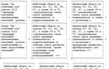
- P0 – main thermal relay modes: heating or cooling, letters C and H, cooling is set by default;
- P1 – hysterisis change: from 0.1 to 15, default 2;
- P2 – maximum positive temperature, default 110 ºС;
- P3 – maximum negative temperature, -50 ºС;
- P4 – correction: -7.0 and 7.0ºС, precise calibration of the temperature range;
- P5 – time delay for turning on and off the thermostat, up to 10 minutes, default 0;
- P6 – limit shutdown temperature, protection against device overheating, disabled by default – OFF.
All information is stored in the board controller, and the settings are saved even if the thermostat is briefly disconnected from the power source.
Resetting to factory settings is carried out by simultaneously pressing the SET, plus and minus keys for some time.
Calibration of thermal relay W1209
It can be done using two known points: the melting temperature of ice – 0ºС and the boiling point of water – 100ºС. It is worth noting that the last parameter is not constant and depends on the air pressure and its rarefaction; this method will not be suitable in the highlands.
Calibrating, checking the W1209, and setting it up at home is quite simple. The sensor is lowered into a container with melting ice or snow, and the setting mode is activated on the thermostat. Next, we set up menu P4, after which we need to repeat the steps at the second control point of 100 degrees Celsius. In this case, you can be sure that the sensor shows a relatively accurate temperature.
Modification of thermostat W1209
Due to the compactness of the main board of the thermostat, the RESET input, the fourth terminal of the controller, is connected to contacts for programming. This leads to the occasional spark throwing off the controller's set values. This drawback is eliminated by installing a 0.1 µF SMD capacitor on a common cable.

Despite the relatively low price, the XH-W1209 thermostat is an effective and compact device for automatic control of temperature conditions. Due to its technical and operational characteristics, it can be used both for various types of technical devices, and directly for temperature control in mini-saunas and baths.

Video
There is such an inexpensive Chinese thermostat W1209. A variety of Chinese stores sell them in fair quantities. One of the advantages is the price :). The rest are a few shortcomings, which can be partially corrected by reprogramming the on-board controller - STM8S003F3.
A thermistor works as a temperature sensor; the standard firmware allows you to enter only a reading offset. Accordingly, for such a thing the accuracy may not be very good (depending on your luck). However, there is a good digital temperature sensor DS18B20, which does not require calibration (well, conditionally). We take such a sensor, modernize the board a little (remove capacitor C1 near the sensor connector, replace resistor R2 with 4.7K). We attach the new sensor to the connector of the old one (there are GND and DQ), we take power from the programming connector (the square penny to the left of the indicator). Plus we upload new firmware - oops, it works :) I note that the original firmware is protected from reading, so it was not possible to save it. There will be no return to the old option. Other users were more fortunate; the Chinese did not block it from being read, so the native firmware is attached below. New - can set the relay response threshold and control method - the relay works if the temperature is lower than the set temperature or if it is higher. Briefly pressing the SET button allows you to set the threshold, holding SET is the control method.
What you will need:
1) ST-Link/V2 programmer. Or any STM8 Discovery board (it is built-in and can be used). The cost on Aliexpress is around 2..4$
2) software for the programmer
http://www.st.com/web/en/catalog/tools/PF260219# (driver)
http://www.st.com/web/catalog/tools/FM147/CL1794/SC1807/SS1747/PF210568 (programming software)
3) a piece of comb with a pitch of 2.54 mm for programming (you can do without it, just solder the wires)
4) resistor size 0805 with a nominal value of 4.7KOhm.
5) the DS18B20 sensor itself.
We are upgrading the thermometer board according to the picture

We take the programmer and connect it to the soldered programming connector (or just wires). Usually on the programmer it is written what goes where. For my version (as an example), see the picture

We get something like in the picture

Launch the ST-Link Visual Programmer program, set the programming parameters

The chip is inherently read/write protected. Need to unlock:
1) Do not supply +12V. powered by st-link.
2) launch the programmer.
3) without attempting to write, try to read the data. (there must be an error, in theory)
4) if yes - the options tab (the third, there is the first program, the second is eeprom, the third is bytes of options) switch to it and make a write page.
5) try to subtract - if everything is fine, the chip will begin to read as zeros and the hardware will stop working completely
Now we write the new firmware.
After the correct connection (can be viewed in), we move on to setting the temperature and other settings.
Depending on what we need to heat or cool (at a given temperature the relay will either close or open the contacts), we set one of two modes: cooling or heating. To do this, press and hold the “SET” button for more than two seconds, the display will show “P0”, this means that we have entered the program menu. The “+” and “-” buttons navigate through the program menu, but in our case we are at the desired value “P0”, so press the “SET” button again and select the desired mode: “C” is cooling, and “H” heat.
The next setting in menu “P1” is hysteresis, this is the temperature difference at which the thermostat turns on or off (factory setting 2°C). For example, the thermostat is set to turn off at +40°C; when this temperature is reached, the relay will open. And it will turn on only when the temperature drops to the set hysteresis, that is, at +38°C.
The next two menu items:
- "P2" is the upper limit for setting the maintained temperature (factory setting +110°C).
- "P3" is the lower limit for setting the maintained temperature (factory setting -55°C). When these temperatures are reached, the W1209 thermostat will be turned off.
Menu item "P5" is responsible for the relay activation time delay, which can be set to 10 minutes. (default setting 0 min).
The last item “P6” allows you to control overheating protection. OFF – protection is disabled, ON – protection is enabled.
Setting the temperature: press the "SET" button, the indicator will start blinking, use the "+" and "-" buttons to set the desired temperature.
To reset to factory settings you need to:
- turn off power
- press and hold the "+" and "-" buttons
- supply power to the thermostat
The LED display will show "888" and then display the current temperature.